 Nerve Blocks App
 Pain Medicine Assistant App
 POCUS App
 IV Access App
 MSK Knee App
 VetRA App
 Nerve Block Manual
 Regional Anesthesia Updates
 Anesthesiology Manual
 Anesthesiology Review
 Anesthesia Updates 2025
 Anesthesia Updates 2026
 Pediatric Anesthesia Updates
 Airway Management Updates
 US Interventional Pain Manual
 Pain Medicine Updates
 Mastering Difficult IV Access
 PACU Nursing Manual
 RA Veterinary Manual
 About
About
Shoulder pain is commonly encountered in pain management practices. Although the rotator cuff and the subacromial structures are thought to contribute to the majority of shoulder pain presentations, there are a number of other structures that generate pain. Fortunately, all these structures are easily accessible with office-based procedures, and injections are useful to confirm the diagnosis and provide analgesia. Ultrasound (US) is particularly suited for addressing shoulder problems. The majority of pain-generating shoulder structures can be visualized with basic US equipment. In particular, the superficial tendons such as long head biceps, supraspinatus, and infraspinatus show excellent echogenicity and structural resolution. Ultrasound permits visualization of soft tissue adjacent to orthopedic hardware, such as total shoulder arthroplasty components. It also gives the clinician the ability to do dynamic assessment of the joint under real-time sonographic imaging. Occult clefts or tendon subluxation may become evident with sonographic assessment during joint motion. Injections of the shoulder must be directed by clinical history, examination, and other imaging modalities. Although US is excellent for imaging the soft tissues, it provides little information about interosseous structures and those shielded by bone. Therefore, plain film imaging is essential for any suspicion of intra-articular pathology (i.e., degenerative joint disease) or osseous pathology such as fractures or bony metastasis. Likewise, sonographic assessment of ligamentous or cartilaginous structures such as the glenoid labrum is very challenging, particularly in large-shouldered patients. Therefore, MRI scanning should be utilized in any case with suspected sinister pathology. In cases with a suspicion for labral tear (posttraumatic or dislocation/subluxation), MRI with intra-articular gadolinium is recommended. Patient safety concerns are minimal for US-guided shoulder injections. Direct complications of shoulder joint injections are extremely rare, although caution should be taken to avoid neurovascular structures, particularly with injections in the anterior shoulder region. The pleura may be at risk for deep injections in the superior shoulder. Finally, injection directly into tendon tissue should be avoided, due to suspected risk of rupture. Fortunately, ultrasound allows continuous visualization of the needle tip, which minimizes risk of inadvertent tendon injection, and assists the clinician in avoiding neurovascular structures. With any injection into a joint or bursa, particular care should be taken to avoid infection. In our current practice, we use a sterile transducer cover on every patient, with iodine gel as the conduction medium between the transducer cover and the skin. We also use sterile gel inside the cover because of two occasions (during resident training), where the needle was accidentally placed through the transducer cover and then into the skin. Most manufacturers will caution against the use of alcohol or iodine/betadine containing products against the transducer due to risk of damage or discoloration. In cases of iodine allergy, we use sterile gel as the conduction medium after skin preparation with chlorhexidine. We also use sterile technique with an operative drape on every patient. Although it is possible to direct a sterile needle under an uncovered probe, we do not recommend this technique, as inadvertent patient movement can easily contaminate the needle and field. In addition, keeping a sterile field allows the clinician to freely adjust transducer position, perform multiple needle passes, and to change the approach if unexpected findings are encountered. This chapter describes the most common shoulder joint injections with sonographic guidance. As in other regions, appropriate sonographic assessment is essential for the guidance of the needle. Major sonographic landmarks and associated pathology will be demonstrated. Transducer placement and needle approaches will be described according to the preferences of the authors, keeping in mind that there are multiple effective approaches for most joints. Finally, and most importantly, the patient’s symptoms and a physical examination must be followed to direct these interventions. Although a complete review of shoulder assessment is outside the scope of this chapter, we have included a brief description of clinical presentation and physical examination findings for each of the syndromes described.
1. SUBACROMIAL/SUBDELTOID BURSA
The subacromial bursa is the most commonly injected structure in the shoulder. Indications include rotator cuff pathology, impingement syndrome, and subacromial bursitis. Subacromial injection of lidocaine is often used to diagnose impingement and offers rationale for subacromial decompression surgery.
2. ANATOMY
The subacromial and subdeltoid bursa typically communicate and effectively function as one bursa. The distal aspect of bursa sits on the upper surface of the supraspinatus muscle, immediately under the deep surface of the deltoid. The bursa functions to protect the supraspinatus as it passes beneath the overlying structures, most notably the acromion process.
3. CLINICAL PRESENTATION
Shoulder abduction and internal rotation can potentially impinge the bursa between the humeral head (greater tubercle) and the arch of the acromion and coracoacromial ligament. This action is reproduced clinically with the Neer and Hawkins–Kennedy impingement tests. In a positive test, pain is reproduced when the humerus is passively elevated (Neer: full flexion in scapular plane with arm internally rotated. Hawkins: flexion to 90 in. in forward plane with arm neutral and elbow bent 90 in. followed by passive internal rotation of the humerus). Impingement can be present with either subacromial bursitis or rotator cuff tendinopathy. However, rotator cuff tendinopathy will typically be more painful with active abduction even within a short arc, while bursitis will be more painful in “impingement” positions and may not be provoked with active abduction below 90°.
4. LIMITATIONS OF THE BLIND APPROACH
Despite being the largest bursa in the body, the accuracy of blind injections has been reported to be as low as 29%, suggesting a high occurrence of false-negative injections. Erroneous placement of the needle in the deltoid muscle, glenohumeral joint, or directly into the cuff tendons has been described. Other studies report accuracy as high as 70% and 83%. Studies have compared the various approaches to the subacromial bursa, and currently, there is no universal consensus on which approach is superior.
5. ULTRASOUND-GUIDED TECHNIQUE
Ultrasound imaging of the subacromial bursa typically starts with the transducer oriented in the coronal/scapular plane and positioned just over the tip of the acromion (Fig. 1a). The supraspinatus tendon should be visualized emerging from beneath the acromion and running over the humerus to attach to the greater tuberosity (Fig.1b). The tendon is hyperechoic when appropriately aligned with the transducer. If the transducer is rocked in a heel-toe motion, the tendon fibrils become less visible (the phenomenon known as “anisotropy”), which may falsely give the appearance of tendon disruption. The bursa is seen as a thin anechoic fluid layer immediately above the tendon (as shown in Fig. 1b), or it may be very thin with intermediate echogenicity. In active bursitis, it may appear thickened relative to the contralateral side. Dynamic assessment may be helpful to visualize the tendon sliding smoothly under the acromion. With gentle active or passive abduction, a “catch” or snap may be appreciated in the presence of mechanical impingement. Dynamic assessment may also reveal clefts in the tendon, which indicate partial or full thickness tears. In the event of a large full thickness tear, the tendon may be absent, atrophic, or retracted. In this instance, an injection in the bursa will communicate directly with the glenohumeral space.
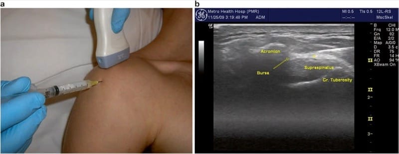
Fig.1 Subacromial/subdeltoid bursa. (a) Transducer positioned over the lateral tip of the acromion and supraspinatus tendon, with needle insertion toward the lateral subacromial space. (b) Needle approaching subacromial bursa. Asterisk indicates ideal end position of needle tip within the subacromial bursa
The sonographer should also make note of calcific densities or clefts within the tendon, which may indicate tendinopathy or tear. Aspiration and lavage of these calcifications under ultrasound guidance have been reported. Ultrasound has been found to be as effective as fluoroscopic guidance for localization of calcifications, and ultrasound can provide a measure of insight into deposit density, which may carry prognostic value.
Injection of the subacromial bursa is performed with the patient in the seated position with the arm hanging at their side (Fig.1a). This allows the joint to be pulled open by the weight of the shoulder. Gentle downward traction on the arm may assist in opening the joint space, and the patient should be reminded to relax the shoulder. Alternatively, the patient’s arm may be placed in the crass position, with the elbow flexed to 90°, arm supinated, and the palm of the hand placed over the ipsilateral hip (as if hand was being placed in the back pocket of pants). The transducer remains in the coronal plane, and the needle is advanced in long axis starting approximately 1 cm lateral to the end of the transducer, maintaining an anterior path between the lateral border of the acromion and the greater tuberosity of the humerus. The needle angle should be adjusted to allow bursal entry just lateral to the acromion (Fig.1a), but bursa entry more distally will typically communicate with the proximal bursa. In very large shoulders, a spinal needle may be necessary, although a 1.5 in. needle is usually sufficient. We typically use a mixture of 1 ml triamcinolone (40 mg/ml) and 2 ml of local anesthetic. Ideally, the injectate is visualized distending the entire bursa with real-time sonography. Fluid may be seen running under the acromion or distally under the deltoid. The diagnosis of impingement or so-called impingement test is confirmed when the patient is reassessed after approximately 15 min, and examination shows reduction in pain with the impingement maneuvers.
6. BICEPS TENDON SHEATH (BICEPS – LONG HEAD)
Anatomy
The long head of the biceps tendon originates at the supraglenoid tubercle of the glenoid labrum and crosses the humerus anteriorly. The head of the humerus has two anterior prominences or tubercles, the lesser tubercle being medial to the greater tubercle. The intertubercular groove runs between the tubercles and houses the bicipital tendon (long head) and is covered by the intertubercular ligament (including extensions of the fibers of the subscapularis muscle). The short head of the biceps originates on the coracoid process in conjunction with the tendon of the coracobrachialis (conjoint tendon). The tendon sheath of the long head tendon communicates proximally with the glenohumeral joint. Therefore injection of the sheath may fill upward into the joint, especially if large volumes of injectate are used. Likewise, glenohumeral joint fluid may flow distally along the tendon in the setting of shoulder joint effusion.
7. ULTRASOUND-GUIDED TECHNIQUE
The long head is first visualized sonographically in cross-section with a linear transducer held in the transverse plane directly over the anterior shoulder (Fig. 2a). The tendon and sheath can then be imaged longitudinally by rotating the probe into the sagittal plane. In this view, the lesser and greater tuberosities are seen “popping up” on either side of the bicipital groove as the transducer is slowly passed from medial to lateral, respectively. With tendon pathology or glenohumeral joint effusion, the tendon sheath will be filled with synovial fluid. If it is non distended, the sheath may offer less than 2 mm clearance to place a needle.
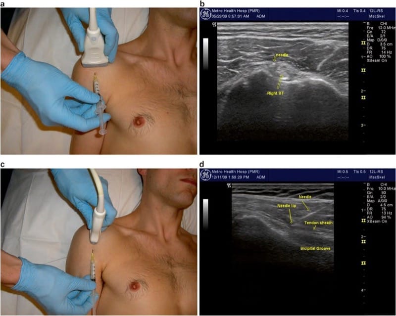
Fig.2 Biceps tendon sheath. (a) Transducer position for transverse imaging of the biceps tendon long head and bicipital groove, and needle insertion just medial to the tendon. (b) Transverse image showing the needle tip just medial to the tendon, deep to the intertubercular ligament. (c) Transducer position for longitudinal approach. (d) Longitudinal view showing the needle approaching the distal aspect of the bicipital groove, directed from distal to proximal (just medial to tendon)
Injection of the bicipital groove can be performed in the short-axis (transverse or out of plane) approach or the longitudinal approach. The short-axis approach is more common and technically easier but does not allow for visualization of the entire length of the needle. After an appropriate setup, the medial side of the bicipital groove is placed in the center of the field of view, and the needle is inserted in the midline of the transducer (Fig. 2a). The target is the small space between the tendon and the lesser tuberosity of the humerus, just medial to the tendon (Fig. 2b). The needle should be directed deep enough (at minimum) to be through the intertubercular ligament and typically is advanced all the way down to contact bone on the floor or medial wall of the groove. Injecting directly over or against the tendon should be avoided with the short-axis approach, as the position of the needle tip may sometimes be in question, and injection of steroid directly into the tendon may lead to rupture. Injection on the lateral aspect of the groove is equally effective as the medial side, but caution should be taken to avoid the ascending branch of the circumflex humeral artery which typically runs up the lateral side of the groove and may be difficult to see due to its small size. If available, power Doppler imaging should be utilized to visualize this structure.
Alternatively, the needle may be advanced in the longitudinal or “in plane” approach, with the tendon visualized along the entire field of view (Fig.2c, d). This approach may be more appropriate for aspiration of the fluid in the sheath, but in our experience, this is rarely clinically necessary. With either approach, the injection is typically completed with a volume of 0.5 ml triamcinolone (40 mg/ml) and 1 ml of local anesthetic. The injectate should be visualized flowing along and around the tendon.
8. ACROMIOCLAVICULAR JOINT
Anatomy
The acromioclavicular or “AC” joint is formed by the articulation of the distal end of the clavicle and the acromion process of the scapula. It is easily palpable by following the clavicle distally until small osteophytes are encountered at the joint margin or a bony step-off is palpated at the joint. In cases of shoulder separation, the step-off may be pronounced, and the clavicle may be high-riding due to tearing of the coracoclavicular ligaments. While this joint may seem easy to localize because of its superficial position, it is often narrowed or shielded by osteophytes. Thus, ultrasound guidance is very helpful. The subacromial bursa and supraspinatus tendon lie directly beneath the joint, often predisposing them to damage from inferiorly directed osteophytes (or needles placed inadvertently through this very small joint).
9. CLINICAL PRESENTATION
AC joint pain typically presents with superior shoulder pain and tenderness directly over the joint. Pain is reproduced with an active elevation of the arm (e.g., changing a light bulb), or with the “scarf” test, where the humerus is passively positioned in crossed-arm adduction (as if throwing a scarf over the contralateral shoulder). Patients who have suffered a shoulder separation, or those that do repetitive upper limb movements, particularly overhead, are prone to AC joint pain. Athletes who do excessive overhead weight lifting are prone to osteolysis of the distal clavicle, which may present very similarly, but will not show on ultrasound imaging, and should not be treated with steroid injection.
10. ULTRASOUND-GUIDED TECHNIQUE
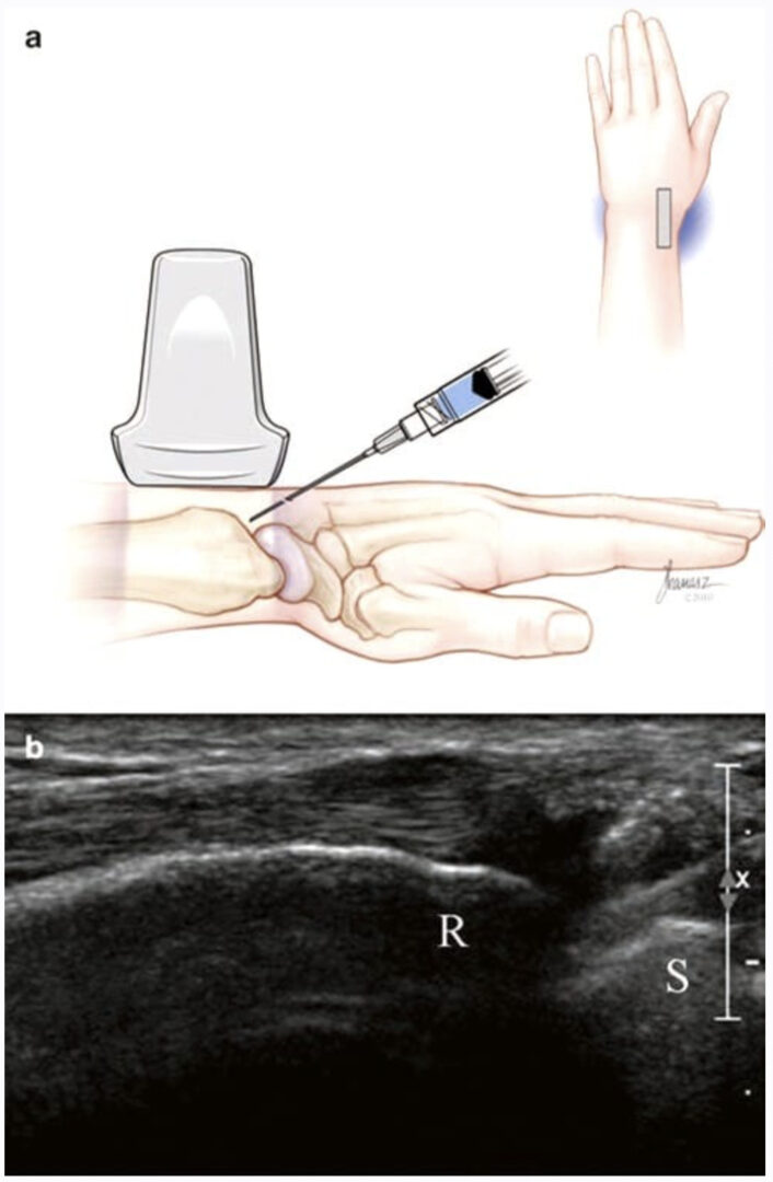
The AC joint is visualized by placing a linear transducer in line with the clavicle and following the clavicle distally until the joint is seen (Fig. 3a). The appearance is typically a “V” shape (Fig. 3b), with the clavicle often projecting superficially compared to the acromion (Fig. 3c). The joint is covered by a thin capsule (acromioclavicular ligament) and may be distended if effusion is present. A small hyperechoic fibrocartilaginous disk can sometimes be visualized within the joint space. There are no significant vascular or neural structures to consider in this injection, but the skin is often thin and friable over the AC joint, so care should be taken not to deposit steroids superficially above the joint.
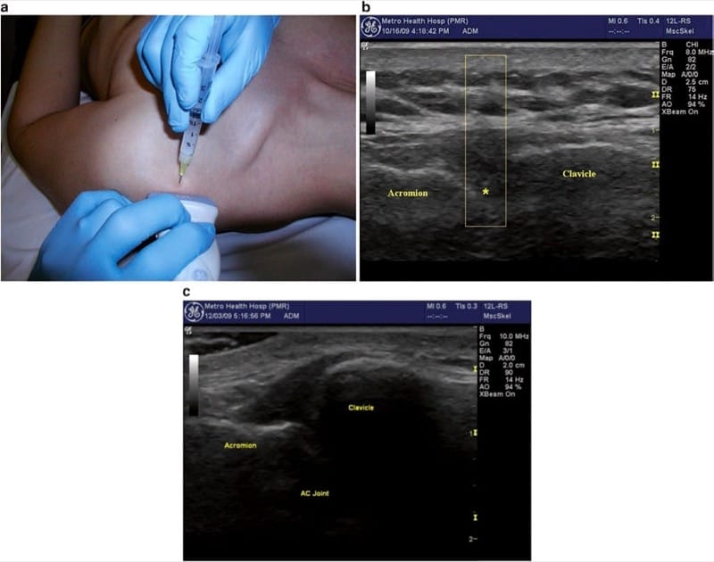
Fig.3 Acromioclavicular joint. (a) Transducer position parallel to the clavicle spanning across the joint with needle insertion at midline of the transducer. (b) Transverse image of AC joint showing the needle shadow and tissue displacement (open rectangle) with needle tip just above asterisk. (c) High-riding clavicle
The patient is best positioned for injection in the seated position with the arm hanging at their side. This allows the joint to be pulled open by the weight of the shoulder. Gentle downward traction on the arm may be helpful to open the joint space but is usually not needed with appropriate sonographic guidance. For accurate needle placement, the “V” shape of the joint should be positioned precisely in the middle of the image, and then the needle is inserted in short-axis orientation, just adjacent to the midline of the transducer from either the anterior or posterior side of the transducer. The needle is directed underneath the transducer so that the tip of the needle is visualized as a bright “dot” as it enters the field of view. Depth is then adjusted by the “walk-down” technique to position the needle tip deep to the capsule, typically, directly between the articulating bony surfaces. Care should be taken to avoid passing the needle completely through the joint, so it is acceptable to position the needle against either wall of the joint. The joint is often completely distended by a very small volume of injectate, so the smallest possible mixture should be used, particularly if the injection is meant for diagnostic purposes. We typically use a mixture of 0.25 ml triamcinolone (40 mg/ml) and 0.75 ml of local anesthetic.
11. GLENOHUMERAL JOINT
Anatomy
The glenohumeral joint or “true shoulder joint” is formed by an articulation between the proximal humeral head and the glenoid cavity. While the true articulation surface is small and shallow, the joint surface area is greatly increased by the presence of the cartilaginous glenoid labrum. The joint is surrounded by a thin fibrous articular capsule, and while strengthened by three glenohumeral ligaments, it remains relatively weak. This allows for a large range of motion at the cost of joint stability. As described under biceps injection above, it should be noted that the joint synovium also extends down the bicipital sheath into the intertubercular groove. Occasionally, the joint capsule also communicates with a subscapular bursa lying on the anterior surface of the scapula.
Glenohumeral joint entry is most commonly performed for injection of degenerative joint disease and adhesive capsulitis. Injections may also be useful for articularsided rotator cuff disease and labral pathology. When effusion is present, aspiration is also very helpful to exclude septic, autoimmune, or crystalline disease of the joint. In many cases, effusion is small, and ultrasound guidance is essential for appropriate localization. Also, periarticular ganglia can often be diagnosed and aspirated with ultrasound guidance.
12. CLINICAL PRESENTATION
Glenohumeral pathology typically presents with painful and restricted range of motion of the joint. The most reliable finding is reduced external rotation with the arm held at the patient’s side, whereas in other shoulder pathologies, the external rotation range of motion is preserved. As with other shoulder pathology, external rotation is nonpainful or minimally painful. It is also very common for glenohumeral disorders to mimic cervical radiculopathy, with referred pain and paresthesias down the entire upper limb even into the digits. In these cases, the Spurling maneuver (neck extension and ipsilateral head rotation toward the affected side) will not change the patient’s pain, while glenohumeral motion will worsen the pain. Glenohumeral pathology often coexists with rotator cuff and biceps pathology, but the pain from the glenohumeral joint typically makes isolation of other coexisting entities clinically difficult.
13. LIMITATIONS OF THE BLIND APPROACH
As with subacromial bursa injections, studies have shown poor accuracy for blind injections of the glenohumeral joint. Sethi et al. reported 26.8% accuracy using an anterior approach. Eustace et al. reported success in 10 of 24 shoulder injections (42%), and Jones et al. reported success in 2 of 20 (10%) attempted injections, though the approach was not disclosed in either study. In contrast, Rutten reported a first attempt success of 94% using ultrasound to guide glenohumeral joint injections. In the same study, Rutten also noted having similar success with the anterior (24 of 25) and posterior (23 of 25) approaches.
14. ULTRASOUND-GUIDED TECHNIQUE
The glenohumeral joint is visualized by a posterior view with the transducer just caudal and parallel to the spine of the scapula (Fig. 4a). The circular humeral head is seen abutting the glenoid fossa with the less-echogenic triangular-shaped labrum between them (Fig. 4b). Gentle rotation of the joint will demonstrate the humeral head rolling on the glenoid and labrum. For very large shoulders, a curvilinear probe with a lower frequency (5–6 MHz) may be necessary. A deeper beam focus and lower frequency are always used relative to other shoulder structures.

Fig.4 Glenohumeral Joint. (a) Transducer positioned on the posterior shoulder, just beneath the spine of the scapula with the arm adducted. (b) Longitudinal needle insertion behind the humeral head (above line), entering the posterior joint just under the glenoid labrum. Asterisk indicates ideal position of needle tip. (c) Transducer position for anterior joint entry through the “rotator interval.” (d) Rotator interval (RCI) with desired needle position (arrow) between the biceps tendon and subscapularis (Sub) tendon. Alternative position indicated by asterisk between SST supraspinatus tendon and biceps tendon. Delt deltoid
Injection of the joint is performed via a posterior approach with the humerus adducted across the thorax, thus opening the posterior joint space (Fig. 4a). It is also very helpful to ask the patient to retract the scapula (i.e., sit or lie with shoulder pulled back in good posture). The transducer is placed as described above, and the needle is inserted in long-axis approach, approximately 2 cm lateral to the lateral heel of the transducer. This lateral entry permits a more shallowangle approach and facilitates visualization of the entire shaft of the needle (Fig. 4b). The target is the space between the glenoid labrum and the humeral head. If the labrum is not well visualized, the needle should be directed toward the humeral head to avoid piercing the labrum or deflecting off the glenoid and away from the joint. Depending upon shoulder size, a 3- or 4-in. (7.5–10 cm) needle is often needed to reach the necessary depth. For larger shoulders, a steeper approach angle may also be required. We have found it helpful to bend the tip of the needle approximately 30°. This facilitates walking of the needle off the posterior aspect of the humeral head. The bent needle is then rotated so that the tip points anteriorly (toward the glenoid) and the needle follows the contour of the humeral head until it lodges deep into the joint. Typically, 1 ml of triamcinolone (40 mg/ml) and 2–5 ml of local anesthetic are injected. Injectate is seen distending the joint capsule, but not flowing extra-articularly or dorsally. Resistance to injection suggests that the needle is embedded into cartilage, and very slight retraction of the needle (with steady pressure on the plunger) will allow free flow of injectate into the joint.
15. THE ROTATOR INTERVAL APPROACH
Anterior visualization of the glenohumeral joint is difficult with most portable equipment, due to increased depth and overlying dense structures. This approach, however, may be worthwhile in patients with joint effusions that present with anterior swelling or in patients with altered anatomy, positioning limitations, or habitus that prohibits posterior joint visualization. For anterior joint entry, the authors recommend a “rotator interval approach.” The rotator interval is a triangular space bordered by the coracoid process, the anterior-most portion of the supraspinatus, and the superior border of the subscapularis tendon. Contained within this triangular space are the biceps tendon, glenohumeral capsule, coracohumeral ligament, and glenohumeral ligament. Recently, Lim et al. reported injecting the GHJ through the rotator interval using ultrasound guidance with good results.
The rotator interval injection is performed with the arm resting at patient’s side and the shoulder placed in slight external rotation. The transducer is positioned in the transverse plane on the superior/anterior shoulder just cranial to the greater and lesser tuberosities of the humerus (Fig. 4c). This position can be found by following the biceps (long head) tendon proximally above the bicipital groove. The transducer is positioned to visualize the intra-articular course of the biceps tendon between the supraspinatus and subscapularis tendons (Fig. 4d). The superior glenohumeral ligament may be visualized between the biceps and subscapularis tendons, whereas the coracohumeral ligament is between the biceps and supraspinatus tendons. The injection is performed after the needle is advanced into the rotator interval between the biceps tendon and the subscapularis tendon (indicated as arrow in Fig.4d). Alternatively, the needle may be placed between the biceps tendon and the supraspinatus tendon (“asterisk” in Fig. 4d). Real-time visualization should show fluid dispersing freely along the humerus and not down the bicipital sheath or anteriorly away from the space. Resistance to injection may indicate that the needle tip has entered a tendon or ligament. Injecting into the rotator interval may be advantageous in very large shoulders. This approach (relative to an injection in the middle of the anterior joint) also avoids many anterior structures such as the subcoracoid bursa, subscapularis muscle and tendon, and the inferior glenohumeral ligament. Furthermore, the needle avoids the anterosuperior labrum by staying lateral to the joint space.
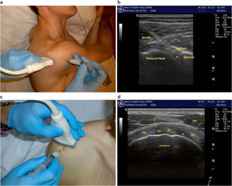
Fig.4 Glenohumeral Joint. (a) Transducer positioned on the posterior shoulder, just beneath the spine of the scapula with the arm adducted. (b) Longitudinal needle insertion behind the humeral head (above line), entering the posterior joint just under the glenoid labrum. Asterisk indicates ideal position of needle tip. (c) Transducer position for anterior joint entry through the “rotator interval.” (d) Rotator interval (RCI) with desired needle position (arrow) between the biceps tendon and subscapularis (Sub) tendon. Alternative position indicated by asterisk between SST supraspinatus tendon and biceps tendon. Delt deltoid
16. SUBSCAPULARIS TENDON/SUBSCAPULARIS BURSA
Anatomy
The subscapularis muscle originates from the subscapular fossa of the scapula and inserts on the lesser tuberosity of the humerus in the anterior shoulder. Some of its fibers continue across the bicipital groove to attach to the greater tuberosity, thereby forming the roof of the bicipital groove. The subscapularis is the only rotator cuff muscle that acts to internally rotate the shoulder. The subscapularis bursa lies deep to the tendon against the neck of the scapula. The bursa usually communicates with the shoulder joint; therefore, it may be distended in the presence of shoulder joint effusion. However, the bursa may be swollen or inflamed in isolation. Occasionally, ganglion cysts or cartilaginous loose bodies are found in this region.
17. CLINICAL PRESENTATION
Subscapularis tendinopathy usually presents with pain in the anterior shoulder and is provoked with active internal rotation or passive external rotation of the shoulder. However, this syndrome is relatively rare and usually does not occur in isolation. Therefore, it is more common for patients to present with diffuse shoulder pain and impingement signs along with localized pain in the region of the subscapularis tendon and bursa.
On physical examination, the patient may have increased tenderness deep in the anterior shoulder just inferior and lateral to the coracoid process. Keep in mind that even normal, asymptomatic patients are tender in this region, so contralateral comparison is essential. Shoulder range of motion is usually preserved. Passive external motion (with the arm at the patient’s side) will stretch the tendon across the anterior shoulder to facilitate palpation, but the deep location of the tendon makes it difficult to palpate. Rarely, a snapping sound or mechanical clunk is detected in this region, which may signify impingement of the subscapularis bursa, a subluxing biceps tendon, a glenoid labral tear, or a loose body in the joint.
Strength of the subscapularis is assessed with the “lift-off test”. The examiner places the affected hand behind the patient’s back (at the level of the waist) with the palm facing posteriorly. Then the patient is asked to lift the hand off the back by internally rotating. Lack of ability to lift the hand indicates subscapularis weakness, tendon rupture, or inadequate range of motion. Pain with this motion is common, so the patient should be asked to precisely localize the painful region.
18. ULTRASOUND-GUIDED TECHNIQUE
Imaging of the subscapularis usually starts with localization of the bicipital groove (see above section on biceps tendon sheath). A linear transducer is held in the transverse position relative to the humerus and bicipital groove (Fig. 5a), and the subscapularis is seen traveling from its deep, medially located muscle belly to attach to the lesser tuberosity. External rotation will pull the tendon across the field of view, and the distal muscular tissue will be seen surrounding the tendon. When the probe is rotated 90° to show the musculotendinous junction, multiple tendon fascicles are seen within the muscle belly, coalescing laterally into the tendon just prior to insertion. The subscapularis bursa may be seen between the tendon and the scapular neck, and in distended shoulder joints, the bursa is commonly seen communicating with the anterior glenohumeral joint.
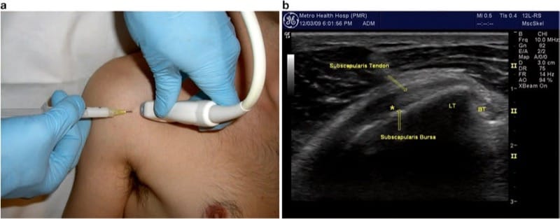
Fig.5 Subscapularis tendon/bursa. (a) Transducer positioned longitudinal to the tendon over the anterior shoulder. (b) Ultrasound image shows the humerus in external rotation with tendon, underlying bursa, and desired needle tip position indicated by asterisk
The tendon and bursa injection can be performed in either the short-axis (transverse or “out of plane”) approach or the longitudinal approach. In the longitudinal approach, a lateral starting position is preferred to avoid the pectoralis muscles and deep neurovascular structures of the axilla. To facilitate visualization and entry, the shoulder should be gently externally rotated (approximately 45°). For the tendon sheath injection, the needle should stop just short of the tendon, with the injectate deposited just anterior to it (indicated as “asterisk” in Fig. 5b). The bursa is reached by advancing the needle through the tendon, at which time a subtle “pop” or give-way is detected. (We typically use a mixture of 0.5 ml triamcinolone (40 mg/ml) and 1 ml of local anesthetic.) When a larger volume is injected in this region, the bursa may be seen distending or the injectate may flow directly into the glenohumeral joint.
19. STERNOCLAVICULAR JOINT
Anatomy
The sternoclavicular or “SC” joint is formed by the articulation of the proximal end of the clavicle with the clavicular fossa in the superior lateral aspect of the sternum. It is easily palpable by following the clavicle proximally where its medial end is usually positioned just anterior to the sternum. With scapular retraction (asking the patient to pull their shoulders back and chest out), the end of the clavicle becomes more prominent, while with protraction (or hunching forward), the clavicle protrudes less. In cases of SC dislocation, the entire end of the clavicle may project anteriorly and medially to the border of the sternum. The great vessels of the chest and the pleura lie deep to the joint, so care is needed to avoid excessive penetration of the needle.
20. CLINICAL PRESENTATION
SC joint pain typically presents with chest wall pain, swelling, and tenderness directly over the joint. Crepitation or subluxation in this region is very common and is not considered pathological unless accompanied by pain or swelling. Pain is reproduced with scapular protraction/retraction, arm elevation, or with the “scarf” test as described for AC joint pain. Patients who have suffered a clavicle fracture and shoulder separation or those that do excessive weight lifting (especially bench presses) are prone to SC joint disease.
21. ULTRASOUND-GUIDED TECHNIQUE
The SC joint is visualized by placing a linear transducer in line with the clavicle and following the clavicle proximally until the joint is seen. The appearance is typically a small notch with the clavicle projecting superficially compared to the sternum. The joint is covered by a very thin capsule and may be distended if effusion is present. The patient is best positioned in the seated position with the arm hanging at their side. Gentle retraction of the scapula may be helpful to open the joint space. A small hyperechoic fibrocartilaginous disk can sometimes be visualized within the joint space and seen subluxing with excessive joint movement.
For SC joint injection, the needle is inserted in short-axis orientation, just adjacent to the transducer. For accuracy, the notch of the joint should both be positioned precisely in the middle of the image and the needle lined up with the corresponding position along the transducer (Fig. 6a). The needle tip is visualized as a bright “dot” as it enters the field of view, hopefully just superficial to the joint (a very shallow angle of approach is required, as the joint is usually very superficially located). Depth is then adjusted by the “walkdown” technique to position the needle tip deep to the capsule, typically, directly between the articulating bony surfaces (indicated as “asterisk” in Fig. 6b). Care should be taken to avoid passing the needle completely through the joint, so that it is acceptable and usually prudent to direct the needle from medial to lateral and stopping if bony contact is made with the end of the clavicle, or adequate depth is visualized. The joint is often completely distended by a very small volume of injectate, so that the smallest possible mixture should be used. We typically use a mixture of 0.25 ml triamcinolone (40 mg/ml) and 0.75 cm3 of local anesthetic.
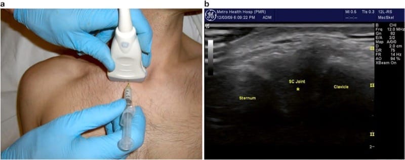
Fig.6 Sternoclavicular joint. (a) Transducer position parallel to the clavicle spanning across the joint with needle insertion at midline of the transducer. (b) Transverse image of AC joint injection showing desired needle tip position indicated by asterisk
22. CONCLUSION
Currently, musculoskeletal ultrasound is still a new and emerging tool. As techniques are further developed, better and varying approaches are expected to develop. Already, there is compelling evidence supporting the merits of ultrasound-guided shoulder injections over “blind” injections and even fluoroscopic guidance. These merits include (but are not limited to) real-time assessment of soft-tissue anatomy, no radiation exposure, direct visualization of needle placement, and flow of injectate. The procedures that have been described are powerful tools in the diagnosis and treatment of shoulder disorders. To provide the best outcome, however, they should be combined with a rehabilitation program to address underlying biomechanical deficits and restore optimal function.
Clinical updates
- Zheng et al. (Trials, 2024) describe a single-center, double-blind RCT (n=78) comparing ultrasound-guided intra-articular botulinum toxin type A (100 IU) versus triamcinolone acetate (1 mL) for post-stroke hemiplegic shoulder pain, with primary outcome change in VAS at 1 and 4 weeks and secondary outcomes including fNIRS-measured cortical oxyhemoglobin changes (DLPFC, M1, S1), Fugl-Meyer upper limb scores, ROM, and MAS. The trial uniquely incorporates functional near-infrared spectroscopy to correlate pain improvement with cerebral hemodynamic changes, aiming to clarify whether intra-articular botulinum toxin modulates central sensitization differently than glucocorticoids.
Zheng P, Shi Y, Qu H, et al. Effect of ultrasound-guided injection of botulinum toxin type A into shoulder joint cavity on shoulder pain in poststroke patients: study protocol for a randomized controlled trial. Trials. 2024;25(1):418.
- Benzon et al. (Reg Anesth Pain Med, 2025) present multisociety guidelines concluding that intra-articular corticosteroid injections provide short-term (weeks to months) pain relief, with no clear superiority among methylprednisolone acetate, triamcinolone hexacetonide, or triamcinolone acetonide, and that extended-release triamcinolone has not shown clinical superiority except for improved post-injection glycemic stability. They recommend lower effective doses (e.g., 20 mg triamcinolone for shoulder IACS; 40 mg for hip; 40 mg triamcinolone equivalent for knee) and highlight risks including hyperglycemia, adrenal suppression, cartilage damage, reduced bone mineral density, and increased postoperative infection risk, with suggested injection intervals of at least 2–3 weeks (commonly 3 months preoperatively).
Benzon HT, Provenzano DA, Nagpal A, et al. Use and safety of corticosteroid injections in joints and musculoskeletal soft tissue: guidelines from the American Society of Regional Anesthesia and Pain Medicine, the American Academy of Pain Medicine, the American Society of Interventional Pain Physicians, and the International Pain and Spine Intervention Society. Reg Anesth Pain Med. Published online March 12, 2025.