André van Zundert and Admir Hadzic
INTRODUCTION
Peripheral nerve stimulation (PNS), an important tool to aid administration of peripheral nerve blocks. Improvements in electrical nerve localization technology have led to a number of commercially available nerve stimulators that are superior and more advanced compared to older devices. With the introduction of ultrasound-guided nerve blocks, however, there has been confusion on the role of nerve stimulation in the setting of ultrasound-guided nerve blocks. This review focuses on the foundation of nerve stimulation with a short historical background, the latest developments in the technology, and the role of nerve stimulation with ultrasound-guided peripheral nerve blocks.
HISTORY
Quick Facts
- 1780: Luigi Galvani was the first to describe the effect of electrical neuromuscular stimulation in a frog experiment.
- 1912: Perthes developed and described an electrical nerve stimulator.
- 1955: Pearson introduced the concept of insulated needles for nerve location.
- 1962: Greenblatt and Denson introduced a portable solid-state nerve stimulator with variable current output and described its use for nerve location.
- 1973: Montgomery et al demonstrated that noninsulated needles require significantly higher current amplitudes than the insulated needles.
- 1984: Ford et al reported a lack of accuracy with noninsulated needles once the needle tip passed the target nerve.
- Ford et al suggested the use of nerve stimulators with a constant current source, based on the comparison of the electrical characteristics of peripheral nerve stimulators.
- In 2004, Hadzic & Vloka defined the electrical characteristics and suggested manufacturing standard for modern nerve stimulators.
It took nearly 100 years from the concept of nerve stimulation to adoption of electrolocalization during peripheral nerve block in the 1990s. The more widespread introduction of nerve stimulation in the practice of peripheral nerve block led to research on the needle-nerve relationship and the effect of stimulus duration. More recently, the principles of electrical nerve stimulation were applied to surface mapping of peripheral nerves using percutaneous electrode guidance for confirmation and epidural catheter placement and peripheral catheter placement. This chapter discusses the electrophysiology of nerve stimulation, electrical nerve stimulators, various modes of localization of peripheral nerves, and integration of the technology into the realm of ultrasound-guided regional anesthesia.
What Is Electrical Peripheral Nerve Stimulation?
Electrical nerve stimulation in regional anesthesia is a method of using a low-intensity (up to 5 mA) and short-duration (0.05 to 1 ms) electrical stimulus (at 1- to 2-Hz repetition rate) to obtain a defined response (muscle twitch or sensation) to locate a peripheral nerve or nerve plexus with an (insulated) needle before injecting local anesthetic in close proximity to the nerve to block nerve conduction for surgery or acute pain management. The use of nerve stimulation can recognize an intraneural or intrafascicular needle placement injection, prevent further needle advancement intraneurally and help reduce the risk of nerve injury.
Electrical nerve stimulation can be used for a single-injection technique, as well as for guidance during the insertion of continuous nerve block catheters. More recently, ultrasound guidance in combination with nerve stimulation (“dual monitoring”) has become a common practice to guide needle placement and robust medicolegal documentation of nerve block procedures.
Indications for the Use of PNS
In principle, almost all plexuses or other large peripheral nerves can be located using PNS. When used with ultrasound guidance, PNS becomes primarily a safety tool. The goal of nerve stimulation is to place the tip of the needle (more specifically, its orifice for injection) in close proximity to the target nerve to inject the local anesthetic within the tissue space that contains the nerve. When used with ultrasound guidance, PNS becomes primarily a safety tool. An unexpected motor response during needle advancement may alert the operator that the needle is in immediate vicinity to the nerve and therefore, prevent further needle advancement when the needle tip position is not well seen on ultrasound. The motor response (twitch) to PNS is objective, reliable and independent from the patient’s (subjective) response. Even with ultrasound guidance, nerve stimulation is often helpful to confirm that the structure imaged is actually the nerve that is sought. Likewise, the needle-nerve relationship may not always be visualized on ultrasound; an unexpected motor response can occur, alerting the operator that the needle is already in close proximity to the nerve. The occurrence of a motor response at a current intensity of less than 0.5 mA can serve as an indicator of a needle-nerve contact or intraneural needle placement. Although this response may not be present even with an intraneural needle position (low sensitivity), its presence is essentially always indicative of intraneural placement (high specificity). An algorithm for using nerve stimulation as a monitoring tool during ultrasound-guided blocks is provided in Figure 1.
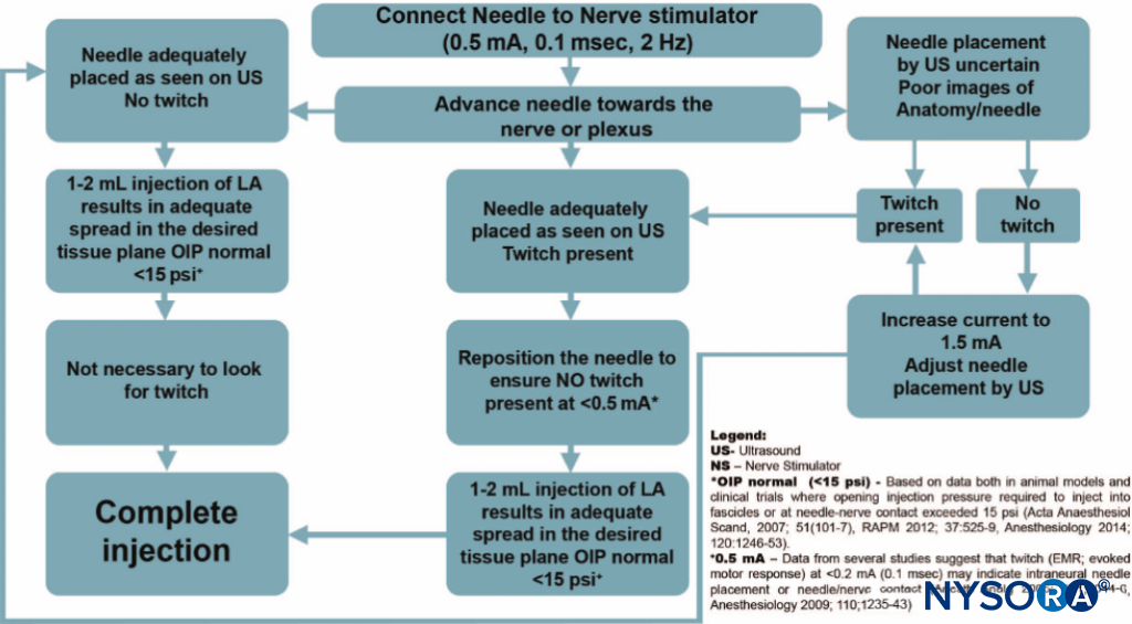
FIGURE 1. An algorithm for use of nerve stimulation with ultrasound-guided nerve blocks. Please note that the nerve stimulator here is used primarily as a safety-monitoring tool, rather than a nerve localization tool. The stimulator is set at 0.5 mA (0.1 ms), and the current is rarely manipulated. Instead, a motor response is obtained; extra caution is exercised as this indicates an intimate needle-nerve relationship. Instead of adjusting the current intensity to determine at which current the motor response extinguishes, the needle is slightly withdrawn to abolish the response and distance the needle tip from the nerve. A small amount of local anesthetic is then injected to determine the needle tip location while avoiding an opening pressure greater than 15 psi. LA, local anesthetic; OIP, opening injection pressure.
The disadvantages of PNS include the need for additional equipment (nerve stimulator and insulated needles), the greater cost of insulated needles, and exceptional cases for which it may be difficult to elicit a motor response.
NYSORA Tips
- Occurrence of a motor response at 0.5 mA (0.1 ms) indicate needle-nerve contact or intraneural needle placement.
- Occurrence of the motor response at 0.5 mA should prompt caution. The practitioner should stop advancing the needle, withdraw the needle by 1 mm, and inject 1 mL of local anesthetic (assuming the opening pressure is less than 15 psi) to determine the needle tip position and adjust the needle and injection process accordingly.
- PNS should not be relied on in a patient receiving muscle relaxants.
- The presence of spinal or epidural anesthesia does not negatively affect the reliability of PNS.
- Multiple injection techniques may decrease PNS sensitivity due to the partial nerve block that occurs between injections.
BASICS OF NEUROPHYSIOLOGY AND ELECTROPHYSIOLOGY
Membrane Potential, Resting Potential, Depolarization, Action Potential, and Impulse Propagation
All living cells have a membrane potential (a voltage potential across their membrane, measured from the outside to the inside), which varies (depending on the species and the cell type) from about –60 to –100 mV. Nerve and muscle cells in mammals typically have a membrane potential (resting potential) of about –90 mV.
Only nerve and muscle cells have the capability of producing uniform electrical pulses, called action potentials (sometimes called spikes), which are propagated along their membranes, especially along the long extensions of nerve cells (nerve fibers, axons). A decrease in the electric potential difference (eg, from –90 to –55 mV, or depolarization) elicits an action potential. If the depolarization exceeds a certain threshold, an action potential or a series of action potentials is generated by the nerve membrane (also called firing) according to the all-or-nothing rule, resulting in propagation of the action potential along the nerve fiber (axon). To depolarize the nerve membrane from outside the cell (extracellular stimulation), the negative polarity of the electrical stimulus is more effective in removing the positive charge from the outside of the membrane. This in turn decreases the potential across the membrane toward the threshold level.
There are various types of nerve fibers. Each fiber type can be distinguished anatomically by its diameter and degree of myelination. Myelination is formed by an insulating layer of Schwann cells wrapped around the nerve fibers. These characteristics largely determine the electrophysiologic behavior of different nerve fibers, that is, the speed of impulse propagation of action potentials and the threshold of excitability. Most commonly, the distinguishing features are motor fibers (eg, Aα, Aβ) and pain fibers (C). The Aα motor fibers have the largest diameter and highest degree of myelination and therefore the highest speed of impulse propagation and a relatively low threshold for external stimulation. The C fibers (which transmit severe, dull pain) have little to no myelination and are of smaller diameter. Consequently, the speed of propagation in these fibers is relatively low, and the threshold levels to external stimulation, in general, are higher.
There are several other efferent fibers, which transmit responses from various skin receptors or muscle spindles (Aδ). These are thinner than Aα fibers and have less myelination. Some of these (afferent) sensory fibers, having a relatively low threshold level, transmit the typical tingling sensation associated with a lower level of pain sensation when electrically stimulated (similar to the sensation when hitting the “funny bone”). Such sensation can occur during transcutaneous stimulation before a motor response is elicited.
The basic anatomic structure of myelinated Aα fibers (motor) and nonmyelinated C fibers (pain) is shown schematically in Figure 2. The relationship between different stimuli and the triggering of the action potential in motor and pain fibers is illustrated in Figures 3A and 3B, respectively.

FIGURE 2. Schematic anatomic structures of nerve fibers. A: Nerve fiber (axon) with insulation (myelin sheath), (Aα fibers). B: Nerve fiber (axon) without insulation (C fiber).
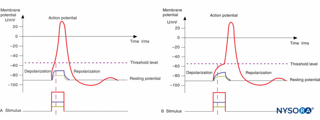
FIGURE 3. A: Action potential, threshold level, and stimulus. Motor fibers have a short chronaxy because of the relatively low capacitance of their myelinated membrane (only the area of the nodes of Ranvier count; see Figure 14–1); therefore, it takes only a short time to depolarize the membrane up to the threshold level. B: Action potential, threshold level, and stimulus. Pain fibers have a long chronaxy because of the higher capacitance of their nonmyelinated membrane (the entire area of the membrane counts); therefore, it takes a longer time to depolarize the membrane up to the threshold level. Short impulses (as indicated by the vertical dotted line) would not be able to depolarize the membrane below the threshold level.
Threshold Level, Rheobase, Chronaxy
A certain minimum current intensity is necessary at a given pulse duration to reach the threshold level of excitation. The lowest threshold current (at infinitely long pulse durations) is called rheobase. The pulse duration (pulse width) at double the rheo-base current is called chronaxy. Electrical pulses with the duration of the chronaxy are most effective (at relatively low amplitudes) to elicit action potentials. This is the reason why motor response can be elicited at such short pulse duration (eg., 0.1 ms) at relatively low current amplitudes while avoiding the stimulation of C-type pain fibers. Typical chronaxy figures are 50–100 μs (Aα fibers), 170 μs (Aδ fibers), and 400 μs or greater (C fibers). The relationship of the rheobase to chronaxy for motor fibers versus pain nerve fibers is illustrated in Figure 4.

FIGURE 4. A: Comparison of threshold curves, chronaxy, and rheobase level of motor (high-speed) and pain (low-speed) fibers. B: Experimental data, threshold amplitudes obtained with percutaneous stimulation (Stimuplex Pen and Stimuplex HNS 12). Stimulation obtained with percutaneous stimulation of the median nerve near the wrist looking for motor response of the thumb. C: Threshold amplitudes obtained with percutaneous stimulation (Stimuplex Pen and Stimuplex HNS 12). Stimulation of the median and radial nerves near the wrist and at the midforearm looking for electric paresthesia (tingling sensation) in the middle and ring fingers (median nerve) or superficial pain sensation near the wrist (radial nerve), respectively.
Impedance, Impulse Duration, and Constant Current
The electrical circuit is formed by the nerve stimulator, the nerve block needle and its tip design, the tissue characteristics of the patient, the skin, the skin electrode (grounding electrode), and the cables connecting all the elements. The resistance of this circuit is not just a simple Ohm’s resistor equation because of the specific capacitances of the tissue, the electrocardiographic (ECG) electrode-to-skin interface, and the needle tip, which influence the overall resistance. The capacitance in the described circuit varies with the frequency content of the stimulation current, and it is called impedance or a complex resistance, which is dependent on the frequency content of the stimulus. In general, the shorter the impulse, the higher its frequency content is and, consequently, the lower the impedance of a circuit with a given capacitance. Conversely, a longer pulse duration has a lower frequency content. As an example, for a 0.1-ms stimulus, the main frequency content is 10 kHz plus its harmonics, whereas for a 1.0-ms impulse, the main frequency content is 1 kHz plus harmonics). In reality, the impedance of the needle tip and the electrode-to-skin impedance have the highest impact. The impedance of the needle tip largely depends on the geometry and insulation (conductive area). The electrode-to-skin impedance can vary considerably between individuals (eg, type of skin, hydration status) and can be influenced by the quality of the ECG electrode used.
Because of the variable impedance in the circuit, created primarily by the needle tip and electrode-to-skin interface, a nerve stimulator with a constant current source and sufficient (voltage) output power is necessary to compensate for the wide range of impedances encountered clinically.
CLINICAL USE OF PERIPHERAL NERVE STIMULATION
Setup and Checking the Equipment
The following are a few important aspects for successful electro-localization of the peripheral nerves using PNS:
- Use only a nerve stimulator specifically manufactured for nerve blocks.
- Use insulated nerve stimulation needles (Table 1).
- Use high-quality skin electrodes with a low impedance.
- Some lower-priced ECG electrodes can have too high an impedance/resistance.
- Before starting the procedure, check for the proper functioning of the nerve stimulator and the connecting cables.
- During the procedure, check frequently to assure that the current is being delivered and leads disconnect does not occur.
- The design of the connectors should prevent a faulty polarity connection.
- Connect the nerve stimulation needle to the nerve stimulator (which should be turned on) and set the current amplitude and duration to the desired levels.
- For superficial blocks, select 1.0 mA as a starting current intensity.
- For deep blocks, select 1.5 mA as a starting current intensity.
- Select between 0.1 and 0.3 ms of current duration for most purposes.
- With ultrasound guidance, select the current as 0.5 mA; it is rarely necessary to change the current as motor response with ultrasound guidance is not sought. However, when unexpectedly elicited, it warns the operator that the needle is in the immediate vicinity of the nerve or intraneurally placed.
TABLE 1. Stimulation needle sizes recommended for various nerve blocks.
| Nerve Block | Single-Shot Technique Length (mm) | Single-Shot Technique Size, OD (mm/G) | Catheter Technique (Introducer Needle) Length (mm) | Catheter Technique (Introducer Needle) Size, OD (mm/G) |
|---|---|---|---|---|
| Anterior interscalene | 25–50 | 0.5–0.7/25–22 | 33–55 | 1.1–1.3/20–18 |
| Posterior interscalene | 80–100 | 0.7/22 | 80–110 | 1.3/18 |
| Vertical infraclavicular (VIB) | 50 | 0.7/22 | 50–55 | 1.3/18 |
| Axillary block | 35–50 | 0.5–0.7/25–22 | 40–55 | 1.3/18 |
| Suprascapular | 35–50 | 0.5–0.7/25–22 | 40–55 | 1.3/18 |
| Psoas compartment | 80–120 | 0.7–0.8/22–21 | 80–150 | 1.3/18 |
| Femoral nerve | 50 | 0.7/22 | 50–55 | 1.3/18 |
| Saphenous nerve | 50–80 | 0.7/22 | 55–80 | 1.3/18 |
| Obturator | 80 | 0.7/22 | 80 | 1.3/18 |
| Parasacral sciatic | 80–120 | 0.7–0.8/22–21 | 80–110 | 1.3/18 |
| Transgluteal sciatic | 80–100 | 0.7–0.8/22–21 | 80–110 | 1.3/18 |
| Anterior sciatic | 100–150 | 0.7–0.9/22–20 | 100–150 | 1.3/18 |
| Subtrochanteric sciatic | 80–100 | 0.7–0.8/22–21 | 80–110 | 1.3/18 |
| Lateral distal sciatic | 50–80 | 0.7/22 | 55–80 | 1.3/18 |
| Popliteal sciatic | 50 | 0.7/22 | 55 | 1.3/18 |
Note: The nerve localization needle sizes given are only estimates; depending on the patient’s size, a slightly shorter or longer size needle may be needed. Some manufacturers also offer smaller needle sizes for pediatric use.
Needles that longer than necessary for a given block procedure should not be used because the risk of complications may increase when inserting the needle too deeply.
Transcutaneous (Surface) Nerve Mapping
When ultrasound guidance is not used, a nerve-mapping pen can be used to locate superficial nerves (up to a maximum depth of approximately 3 cm) with transcutaneous nerve stimulation before the nerve block needle is inserted. Transcutaneous nerve mapping is particularly useful when identifying the best site for needle insertion in patients with difficult anatomy or when the landmarks prove difficult to identify. Figure 5 shows several available nerve-mapping pens.
Nerve mapping is also useful when teaching surface anatomy. It should be noted that longer stimulus duration (eg, 1 ms) is needed to accomplish transcutaneous nerve stimulation, as larger energy is required to elicit a motor response from the neural structures transcutaneously. The electrode tip of the pen should have an atraumatic, ball-shaped tip. The conductive tip diameter should not be larger than approximately 3 mm to provide sufficient current density and spatial discrimination, which may not be the case with larger tip diameters. Be aware that many nerve stimulators do not provide the required impulse duration of 1 ms or a strong enough constant current source (5 mA at minimum, 12 kΩ output load) to reliably use a nerve-mapping pen. Therefore, it is recommended that the mapping pen and the nerve stimulator be paired, ideally, by acquiring them from the same manufacturer.
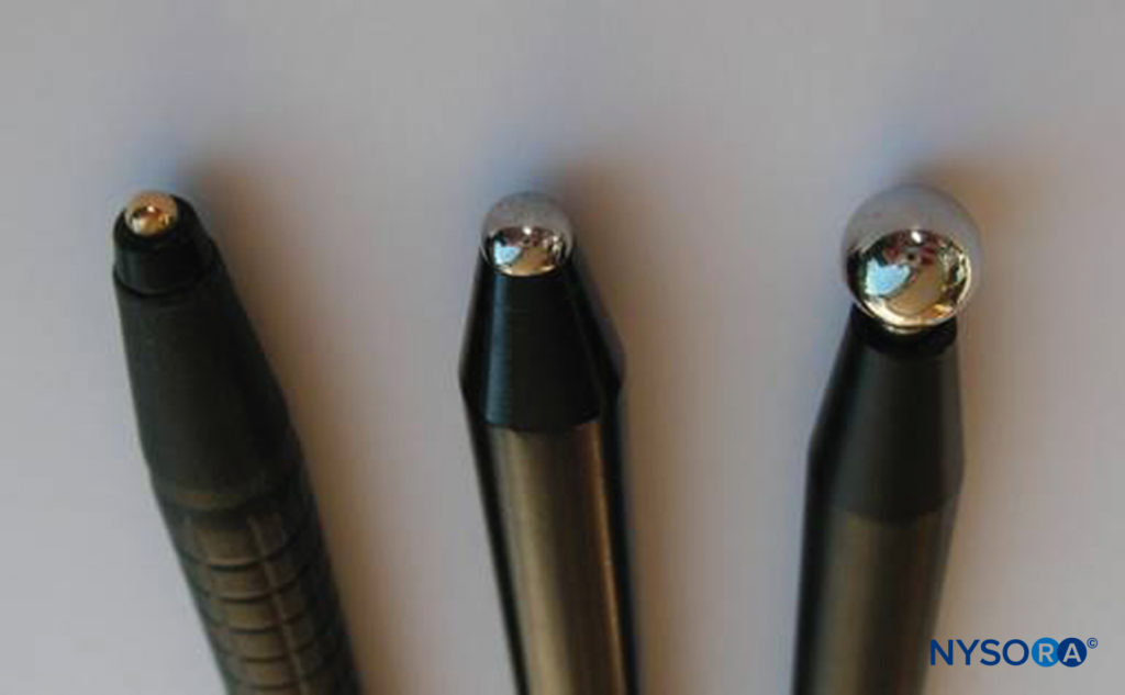
FIGURE 5. Tip configuration of several commercially available nerve-mapping PNS. From left to right: Stimuplex Pen (B. Braun, Melsungen (Germany); nerve-mapping pen (Pajunk, Germany); NeuroMap (HDC, USA).
The transcutaneous stimulation from a nerve-mapping pen can cause several kinds of sensation due to the stimulation of various sensory cells in the skin. This may be felt as tingling, a pinprick, or even a slight burning sensation. The perception varies greatly between individuals. Most patients tolerate transcutaneous stimulation with a nerve-mapping pen well; however, some individuals describe it as uncomfortable or even painful (depending on the stimulus amplitude and duration). However, the amount of energy delivered by nerve stimulators with a maximum output of 5 mA at 1-ms pulse duration is far too low to create any injury of the skin or the nerves. Moderate premedication is usually sufficient to make the procedure well tolerated by patients. Surface mapping was suggested as a useful tool in residents’ training and particularly became popular in pediatric regional anesthesia in the 2000s. However, its use has been infrequent with the advent of ultrasound guidance.
Percutaneous Electrode Guidance
Percutaneous electrode guidance combines transcutaneous nerve stimulation (nerve mapping) with nerve block needle guidance. In essence, a small aiming device is mounted and locked onto a conventional nerve block needle, which allows the conductive needle tip to make contact with the skin without scratching or penetrating the skin. Once the best response is obtained, the needle is advanced through the skin in the usual fashion, and the remainder of the apparatus continues to stabilize the needle and guide it toward the target. The device also allows the operator to make indentations in the skin and tissue so that the initial distance between the needle tip at the skin level and the target nerve is reduced, and the nerve block needle has less distance to travel through tissue. The technique allows for prelocation of the target nerve(s) prior to skin puncture (Figure 6).
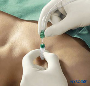
FIGURE 6. Percutaneous electrode guidance technique using Stimuplex Guide (B. Braun, Melsungen, Germany) during a vertical infraclavicular block procedure.
Operating the Nerve Stimulator
The starting amplitude used for nerve stimulation depends on the local practice and the projected skin-nerve depth. For superficial nerves, an amplitude of 1 mA to start is chosen in most cases. For deeper nerves, it may be necessary to increase the initial current amplitude between 1.5 and 3 mA until motor response is elicited at a safe distance from the nerve. Too high current intensity, however, can lead to direct muscle stimulation or discomfort for the patient, both of which are undesirable.
Once the sought-after muscle response is obtained, the current intensity amplitude is gradually reduced, and the needle is slowly advanced farther. The needle must be advanced slowly to avoid too rapid advancement between the stimuli. Advancement of the needle and current reduction are continued until the desired motor response is achieved with a current of 0.2–0.5 mA at 0.1-ms stimulus duration. The threshold level and duration of the stimulus are interdependent; in general, a short pulse duration is a better discriminator of the distance between the needle and the nerve. When the motor twitch is lost during needle advancement, the stimulus intensity first should be increased to regain the muscle twitch rather than move the needle blindly. Once the needle is positioned properly, close enough to the nerve at around 0.3-mA current amplitude and 0.1-ms pulse duration, 1–2 mL of local anesthetic is injected as a test dose using low opening injection pressure, which abolishes the muscle twitch. The highly conductive injectate (eg, local anesthetic or normal saline solution) short-circuits the current to the surrounding tissue, effectively abolishing the motor response. In such situations, increasing the amplitude may not bring back the muscle twitch. Tsui and Kropelin demonstrated that injection of dextrose 5% in water (D5W; which has low conductivity) does not lead to loss of the muscle twitch if the needle position is not changed. Then, the total amount of local anesthetic appropriate for the desired nerve block is injected.
It should be remembered that the absence of the motor response with a stimulating current of up to 1.5 mA does not rule out intraneural needle placement (low sensitivity). However, the presence of a motor response with a low-intensity current (≤0.2 mA, 0.1 ms) occurs only with intraneural and, possibly, intrafascicular needle placement. For this reason, if the motor response is still present at 0.2 mA or less (0.1 ms), the needle should be slightly withdrawn to avoid the risk of intrafascicular injection. The principle of the needle-to-nerve approach and its relation to the stimulation is depicted in Figures 7A, 7B, and 7C.
To avoid or minimize discomfort for the patient during the nerve location procedure, it is recommended that too high stimulating current be avoided. Again, the needle should not be advanced too fast because this can increase the risk of injury. Also, the best needle position, producing a good near-threshold motor response, may be missed.
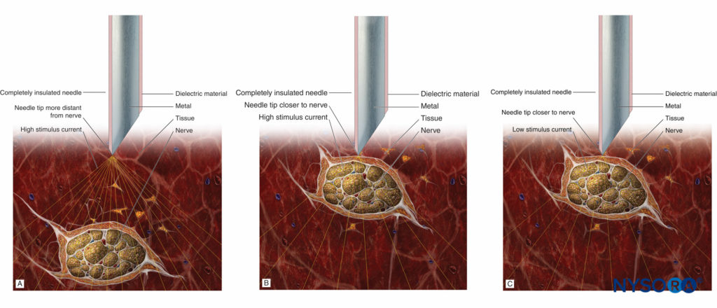
FIGURE 7. A: Stimulation needle at a distance to the nerve and high stimulus current eliciting a weak motor response. B: Stimulation needle close to the nerve and high stimulus current eliciting a strong motor response. C: Stimulation needle close to the nerve and low (near-threshold) stimulus current eliciting a weak motor response.
The Role of Impedance Measurement
Measurement of the impedance can provide additional informa-tion if the electrical circuit is optimal. Theoretically, impedance can identify intraneural or intravascular placement of the needle tip. Tsui and colleagues reported that the electrical impedance nearly doubles (12.1 to 23.2 kΩ), which is significant, when the needle is advanced from an extraneural to intraneural position in a porcine sciatic nerve. Likewise, injection of a small amount of D5W, which has a high impedance, results in a significantly higher increase of impedance in the perineural tissue than it does within the intravascular space. Thus, measurement of the impedance before and after dextrose injection can potentially detect intravascular placement of the needle tip, thus identifying the placement prior to the injection of local anesthetic. In this report, the perineural baseline impedance (25.3 ± 2.0 kΩ) was significantly higher than the intravascular (17.2 ± 1.8 kΩ). On injection of 3 mL of D5W, the perineural impedance increased by 22.1 ± 6.7 kΩ to reach a peak of 50.2 ± 7.6 kΩ and remained almost constant at about 42 kΩ during the 30-s injection time. By contrast, intravascular impedance increased only by 2.5 ± 0.9 kΩ, which is significantly less compared to the perineu-ral needle position. At present, however, more data are needed before these findings can be incorporated as an additional safety-monitoring method in clinical practice, although there have been significant recent advances in this regard.
Sequential Electrical Nerve Stimulation
Current nerve stimulation uses stimuli of identical duration (typically 0.1 ms), usually at 1- or 2-Hz repetition frequency. A common problem during nerve stimulation is that the evoked motor response is often lost while moving the needle to optimize its position. In such cases, it its recommended that the operator either increase the stimulus amplitude (mA) or increase the impulse duration (ms), the latter of which may not be possible. Alternatively, the operator can take a couple of steps, depending on the type of nerve stimulator used. The SENSe (sequential electrical nerve stimulation) technique incorporates an additional stimulus with a longer pulse duration after two regular impulses at 0.1-ms duration, creating a 3-Hz stimulation frequency. The third longer impulse delivers more charge than the first two and therefore has a longer reach into the tissue. Consequently, an evoked motor response often is elicited at 1 Hz, even when the needle is distant from the nerve. Once the needle tip is positioned closer to the nerve, muscle twitches are seen at 3 Hz. The advantage of the SENSe technique is that a motor response (at 1/s) is maintained even when the twitches previously elicited by the first two impulses are lost due to slight needle movement. This feature prevents the operator from moving the needle “blindly.”
Figure 8 shows examples of the particular SENSe impulse patterns at different stimulus amplitudes. Eventually, the target threshold amplitude remains the same as usual (about 0.3 mA) but at 3 stimuli per second. With the SENSe technique, a motor response at only 1/s indicates that the needle is not yet placed correctly. Similar to the surface mapping, the utility of this technology has substantially decreased.

FIGURE 8. Sequential Electrical Nerve Stimulation (SENSe) impulse pattern of the Stimuplex HNS 12 nerve stimulator (B. Braun, Melsungen, Germany) depending on the actual stimulus amplitude. The impulse duration of the third impulse decreases with the stimulus amplitude below 2.5 mA from 1.0 ms to a minimum of 0.2 ms compared to the constant impulse duration of 0.1 ms of the first two impulses. A: Impulse pattern at 0.3 mA (threshold level). B: Impulse pattern at 1.0 mA. C: Impulse pattern at 2.0 mA.
Troubleshooting During Nerve Stimulation
Table 2 lists the most common problems encountered during electrolocalization of the peripheral nerves and the corrective action.
TABLE 2. Common problems encountered during electrolocalization of peripheral nerves and corrective action.
| Problem | Solution |
|---|---|
| Nerve stimulator does not work at all. | Check and replace battery; refer to stimulator operator’s manual. |
| Nerve stimulator suddenly stops working | Check and replace battery. |
| No motor response is achieved despite the appropriate needle placement. | Check connectors, skin electrode, cables, and stimulation needle for an interrupted circuit or too high impedance. |
| Check and make sure that current is flowing—no disconnect indicator on the stimulator. | |
| Check the setting of amplitude (mA) and impulse duration. | |
| Check stimulator setting (some stimulators have a test mode or pause mode, which prevents current delivery). | |
| Motor response disappears and cannot be regained even after increasing stimulus amplitude and duration. | Check for the causes listed previously. Can be caused by injection of local anesthetic. |
CHARACTERISTICS OF MODERN NERVE STIMULATORS FOR NERVE BLOCKS
Most Important Features of Nerve Stimulators
This section addresses the most important features of nerve stimulators for monitoring during nerve block procedures.
Electrical Features
- An adjustable constant current source with an operating range of 10 kΩ, minimally, output load (impedance), and ideally at 15 kΩ or greater.
- Adjustable stimulus amplitude (0–5 mA).
- A large and easy-to-read digital display of actual current delivered.
- A selectable pulse duration (width), at least between 0.1 and 1.0 ms (motor fibers are stimulated more easily with currents of shorter duration [0.1 ms] whereas sensory fibers require a longer stimulus duration [1.0 ms]).
- A stimulus frequency between 1 and 3 Hz (meaning 1 to 3 pulses per second). The best compromise is 2 Hz, which should be the default
- A monophasic rectangular output pulse to provide reproducible stimuli.
- Configurable startup parameters so that the machine will comply with the hospital protocol and to avoid mistakes when multiple users are working with the same device (0.5 mA on startup, 0.1-ms pulse duration, 2-Hz stimulating frequency).
- A display of the circuit impedance (kΩ) is recommended to allow the operator to check the integrity of the electrical circuit and to detect a potential intraneural or intravascular placement of the needle tip.
- An automatic self-check process of the internal functioning of the unit with a warning message if something is wrong with the circuit.
Safety Features
- Easy and intuitive use.
- A large and easy-to-read display.
- Limited current range (0–5 mA) because an amplitude that is too high may be painful or uncomfortable for the patient.
- A display of all relevant parameters, such as amplitude (mA) (alternatively stimulus charge [nC]), stimulus duration (ms), stimulus frequency (Hz), impedance (kΩ), and battery status.
- Clear identification of output polarity (negative polarity at the needle).
- Meaningful instructions for use, with lists of operating ranges and allowed tolerances.
- Battery operation of the nerve stimulator, as opposed to electrical operation, provides intrinsic safety; there is no risk of serious electric shock or burns caused by a short circuit to the main supply of electricity.
- The maximum energy delivered by a nerve stimulator with 5 mA and 95-V output signal at 1-ms impulse duration is only 0.475 mWs.
- Combined units for peripheral (for peripheral nerve block) and transcutaneous (for muscle relaxation measurement) electrical nerve stimulation should not to be used because the transcutaneous function produced an unwanted high energy charge.
Alarms/warnings:
- Open circuit/disconnection alarm (optical and acoustic).
- Warning/indication if impedance is too high, that is, the desired current is not delivered.
- Displaying actual impedance is advisable.
- Near-threshold amplitude indication or alarm.
- Low-battery alarm.
- Internal malfunction alarm.
Table 3 provides a comparison of the most important features of commonly used nerve stimulators.
TABLE 3. Comparison of most relevant features of modern nerve stimulators.
| Product/company Feature | Stimuplex HNS 12 (w/ SENSe) B. Braun | Stimuplex HNS 11 (replaced by HNS 12) B. Braun | Stimuplex DIG RC B. Braun | Multistim Sensor Pajunk | Multistim Vario Pajunk | Multistim Plex Pajunk | Plexygon Vygon | Polystim II Polymedic | Tracer III Life-Tech | NeuroTrace III / NMS 300 HDC/Xavant technology |
|---|---|---|---|---|---|---|---|---|---|---|
| Amplitude setting | Digital dial, 1 or 2 turns for full scale | Analog dial | Analog dial | Digital dial | Up/down keys | Up/down keys | Digital dial up/down keys | Analog dial | Analog dial | Up/down keys |
| Display size [WxH, mm] / type | 62 × 41 graphic LCD | 50 × 20 standard LCD | 21 × 8 red LED | 47 × 36 custom LCD | 47 × 18 custom LCD | 47 × 18 custom LCD | 47.5 × 33.5 custom LCD | 50 × 20 standard LCD | 50 × 20 standard LCD | 41 × 22 graphic LCD |
| Current range [mA] | 0-1 0-5 | 0-1 0-5 | 0.2-5 | 0-6 0-60 (for nerve mapping only, max. 1 kOhm) | 0-6 0-60 (for TENS only, max. 1.3 kOhm) | 0-6 | 0-6 (at 0.05 ms) 0-5 (at 0.15 ms) 0-4 (at 0.3 ms) | 0-1 0-5 | 0.05-5 0.05-1.5 (w/ foot pedal) | 0.1-5 0-20 (nerve mapping) 0-80 (TENS) |
| Max. output voltage [V] | 95 | 61 | 32 | 65 | 80 | 80 | 48 | 72 | 60 | 400 (for TENS) |
| Max. output load (impedance) nominal/max. | 12/17 kOhm (5 mA) 90 kOhm (1 mA) | 12/12 kOhm (mA) 60 kOhm (mA) | 6/6 kOhm (5 mA) 30 kOhm (mA) | 12/13 kOhm (5 mA) 65 kOhm (1 mA) | 12/15 kOhm (5 mA) 80 kOhm (1 mA) | 12/15 kOhm (5 mA) 80 kOhm (1 mA) | 9/9 kOhm (5 mA) 48 kOhm (1 mA) | 10/13 (5 mA) 72 kOhm (1 mA) | 12/11 kOhm (5 mA) | 80 kOhm (5 mA) (for TENS) |
| Impulse duration [ms] | 0.05, 0.1, 0.3, 0.5, 1.0 | 0.1, 0.3, 1.0 | 0.1 | 0.05, 0.1, 0.2, 0.3, 0.5, 1.0 | 0.1, 0.3, 0.5, 1.0 | 0.1 | 0.05, 0.15, 0.3 | 0.1, 0.3, 1.0 | 0.05, 0.1, 0.3, 0.5, 1.0 | 0.04-0.200 |
| Stimulus frequency [Hz] | 1, 2, 3 (SENSe) | 1, 2 | 1, 2 | 1, 2 | 1, 2, TOF, 50Hz, 100 Hz | 1, 2 | 1, 2, 4 | 1, 2, 3, 4, 5 | 1, 2 | 1, 2 TOF, DB, 50Hz, 100 Hz |
| Display of patient current | YES | YES activated by key | NO | YES | YES activated by key | NO | YES | YES | NO | NO |
| Display of set current | YES if patient current is lower | YES activated by key | YES flashes if patient current is lower | YES if PAUSE key is pressed, or dial is turned | YES activated by key | YES (permanent) | YES if dial is turnd | YES activated by key | YES | YES no indication if patient current deviates from displayed value |
| Display of impulse duration (ms) | YES | YES key LED | - | YES | YES | - | YES | YES key LED | YES | NO |
| Display of impedance | 0-90 kOhm | NO | NO | NO | NO | NO | NO | NO | NO | NO |
| Display of charge (nC) | Optional, in addition to display of mA | NO | NO | NO | NO | NO | Alternative to mA | NO | NO | NO |
| Alarm signals | Special alarm and warning sounds; LED (red/yellow/green), display of respective text messages | Change of beep tone and LED stops flashing when no current, display icon | No tone and no yellow LED flash if no current; blinking display if current is lower than set | Change of beep tone if no current, display icon | Change of beep tone, display symbol, LED stops flashing if no current | Change of beep tone, display symbol, LED stops flashing if no current | Constant tone if open circuit, flashing display if current is lower than set | Click tone changes, LED stops flashing when current is lower than set | Flashing display and chirp sounds on open circuit | Chirp tone and display symbol for open circuit; no indication if current is lower than set |
| Threshold amplitude warning | Acoustic, LED yellow and display of text message | NO | NO | NO | NO | NO | NO | NO | NO | NO |
| Menu for setup and features | YES, full text menu, 26 languages | NO | NO | NO (setup w/o menu) | NO | NO | NO | NO | NO | YES, limited text |
| Percutaneous nerve mapping | YES stimuplex pen | YES stimuplex pen | NO | YES Pen + bipolar probe | NO | NO | NO | NO | NO | YES NeuroMap pen |
| Remote control | Handheld RC | NO | Handheld RC | NO | NO | NO | NO | NO | Foot pedal RC | NO |
| Power consumption at 5 mA output [mA] | 3.6 | 3.6 (key LEDs off ) | 6.0 | 4.8 | 4.2 | 5.0 | 15.5 | 11.8 (key LEDs off ) | No data | 5.7 |
| Size H × W × D [mm] | 157 × 81 × 35 | 145 × 80 × 39 | 126 × 77 × 38 | 120 × 65 × 22 | 121 × 65 × 22 | 122 × 65 × 22 | 200 × 94 × 40 | 245 × 80 × 39 | 153 × 83 × 57 | 125 × 80 × 37 |
| Weight w/ battery [g] | 277 | 266 | 210 | 167 | 168 | 169 | 251 | 247 | 275 | 235 |
Stimulating Needles
A modern stimulating needle should have the following characteristics:
- A fully insulated needle hub and shaft to avoid current leakage
- Depth markings for easy identification and documentation of the needle insertion depth
Figures 9A and 9B show a comparison of the electrical characteristics of noninsulated and insulated needles with uncoated bevel (Figure 9A) and fully coated needles with a pinpoint electrode (Figure 9B). Even though a noninsulated needle provides for some discrimination (change in threshold amplitude) while approaching the nerve, there is virtually no ability to discriminate once the needle tip has passed the nerve. Therefore, spatial discrimination near the nerve is more precise in needles with a pinpoint electrode tip (Figure 9B) compared to needles with an uncoated bevel (Figure 9A).

FIGURE 9. A: Threshold amplitude achieved with an uncoated needle and a coated needle with an uncoated bevel. B: Threshold amplitude achieved with a fully coated needle and a pinpoint electrode.
Connectors
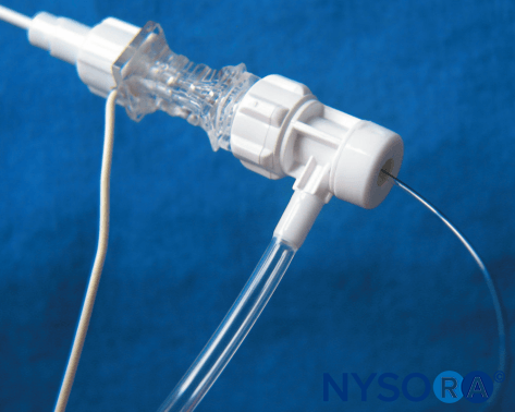
Connectors and cables should be fully insulated and include a safety connector to prevent current leakage as well as the risk of electric charge if the needle is not connected to the stimulator. Extension tubing with a Luer lock connector should be present for immobile needle technique.
Visualization of the Needle Under Ultrasound Imaging
Because ultrasound imaging is used more frequently (in particular with the use of the “dual-guidance” technique), the importance of good visualization of the nerve block needle is becoming an additional important feature. The visibility (distinct reflection signal) of the needle tip certainly is the most important aspect because this is the part of the needle that is placed in the target area next to the nerve. However, in particular when using the in-plane approach, the visibility of the needle shaft is of interest as well because it helps to align the needle properly with the ultrasound beam to visualize the entire length to the target nerve.
Stimulating Catheters
In principle, stimulating catheters function like insulated needles. The catheter body is made from insulating plastic material and usually contains a metallic wire inside, which conducts the current to its exposed tip electrode. Usually, such stimulating catheters are placed using a continuous nerve block needle, which is placed by first using nerve stimulation as described. It acts as an introducer needle for the catheter. Once this needle is placed close to the nerve or plexus to be blocked, the stimulating catheter is introduced through it, and the nerve stimulator is connected to the catheter. Stimulation through the catheter should reconfirm that the catheter tip is positioned in close proximity to the target nerve(s). However, it must be noted that the threshold currents with stimulating catheters may be considerably higher. Injection of local anesthetic or saline (which is frequently used to widen the space for threading the catheter more easily) should be avoided because this may increase the threshold current considerably and can even prevent a motor response. D5W can be used to avoid losing a motor response. Since the introduction of ultrasound monitoring of the distribution of the local anesthetic after needle or catheter placement, stimulating catheters have become nearly obsolete. This is because the ultimate test of the placement of the catheter tip in the therapeutic position is the distribution of the injectate in the tissue plane that contains the nerve or the plexus. Because the stimulating catheter can be placed in the proper position without obtaining the motor response, using the stimulation through the catheter will often lead to unnecessary needle and catheter manipulation. Nerve stimulation monitoring of the single-injection or continuous needle placement is useful to avoid needle-nerve contact or intraneural placement and help decrease the risk of nerve inflammation or intraneural injection and consequent injury. In contrast, catheters are pliable and highly unlikely to cause nerve trauma or be inserted into a fascicle.
NYSORA Tips
- Use low-intensity current nerve stimulation (0.5 mA) with ultrasound-guided nerve blocks and do not change the current intensity during the procedure.
- For nerve stimulator–guided nerve blocks, adjust the stimulus current amplitude: 1 mA (superficial blocks), 2 mA (deeper blocks) (eg, psoas compartment and deep sciatic blocks), 0.1 ms.
- Do not inject if the threshold current is 0.2–0.3 mA or less (0.1 ms) or opening injection pressure.
For a more comprehensive review, continue reading: Monitoring, Documentation, and Consent for Regional Anesthesia Procedures.
REFERENCES
- Luigi Galvani (1737–1798). n.d. http://en.wikipedia.org/wiki/Galvani.
- von Perthes G: Überleitungsanästhesie unter Zuhilfenahme elektrischer Reizung. Munch Med Wochenschr 1912;47:2545–2548.
- Pearson RB: Nerve block in rehabilitation: A technique of needle localization. Arch Phys Med Rehabil 1955;26:631–633.
- Greenblatt GM, Denson JS: Needle nerve stimulator locator. Nerve blocks with a new instrument for locating nerves. Anesth Analg 1962;41:599–602.
- Montgomery SJ, Raj PP, Nettles D, Jenkins MT: The use of the nerve stimulator with standard unsheathed needles in nerve block. Anesth Analg 1973;52:827–831.
- Ford DJ, Pither C, Raj PP: Comparison of insulated and uninsulated needles for locating peripheral nerves with a peripheral nerve stimulator. Anesth Analg 1984;63:925–928.
- Ford DJ, Pither CE, Raj PP: Electrical characteristics of peripheral nerve stimulators: Implications for nerve localization. Reg Anesth 1984;9:73–77.
- Pither CE, Ford DJ, Raij PP: The use of peripheral nerve stimulators for regional anesthesia, a review of experimental characteristics, technique, and clinical applications. Reg Anesth 1985;10:49–58.
- Hadzic A, Vloka JD, Claudio RE, Thys DM, Santos AC: Electrical nerve localization: Effects of cutaneous electrode placement and duration of the stimulus on motor response. Anesthesiology 2004;100:1526–1530.
- Kaiser H, Neuburger M: How close is close enough—How close is safe enough? Reg Anesth Pain Med 2002;27:227–228.
- Neuburger M, Rotzinger M, Kaiser H: Electric nerve stimulation in relation to impulse strength. A quantitative study of the distance of the electrode point to the nerve. Acta Anaesthesiol Scand 2007;51:942–948.
- Bosenberg AT, Raw R, Boezaart AP: Surface mapping of peripheral nerves in children with a nerve stimulator. Paediatr Anaesth 2002;12:398–403.
- Urmey WF, Grossi P: Percutaneous electrode guidance. A non-invasive technique for prelocation of peripheral nerves to facilitate peripheral plexus or nerve block. Reg Anesth Pain Med 2002;27:261–267.
- Urmey WF, Grossi P: Percutaneous electrode guidance and subcutaneous stimulating electrode guidance. Modifications of the original technique. Reg Anesth Pain Med 2003;28:253–255.
- Capdevilla X, Lopez S, Bernard N, et al: Percutaneous electrode guidance using the insulated needle for prelocation of peripheral nerves during axillary plexus blocks. Reg Anesth Pain Med 2004;29:206–211.
- Tsui BC, Gupta S, Finucane B: Confirmation of epidural catheter placement using nerve stimulation. Can J Anesth 1998;45:640–644.
- Tsui BC, Guenther C, Emery D, Finucane B: Determining epidural catheter location using nerve stimulation with radiological confirmation. Reg Anesth Pain Med 2000;25:306–309.
- Tsui BC, Seal R, Koller J, Entwistle L, Haugen R, Kearney R: Thoracic epidural analgesia via the caudal approach in pediatric patients undergoing fundoplication using nerve stimulation guidance. Anesth Analg 2001;93:1152–1155.
- Boezaart AP, de Beer JF, du Toit C. van Rooyen K: A new technique of continuous interscalene nerve block. Can J Anesth 1999;46:275–281.
- Kaiser H. Periphere elektrische Nervenstimulation. In Niesel HC, Van Aken H (eds): Regionalanästhesie, Lokalanästhesie, Regionale Schmerztherapie, 2nd edi. Thieme, 2002.
- Gadsden J, Latmore M, Levine DM, Robinson A: High opening injection pressure is associated with needle-nerve and needle-fascia contact during femoral nerve block. Reg Anesth Pain Med 2016;41:50–55.
- Gadsden JC, Choi JJ, Lin E, Robinson A: Opening injection pressure consistently detects needle-nerve contact during ultrasound-guided interscalene brachial plexus block. Anesthesiology 2014;120:1246–1253.
- Tsui BC, Kropelin B: The electrophysiological effect of dextrose 5% in water on single-shot peripheral nerve stimulation. Anesth Analg 2005;100:1837–1839.
- Tsui BC: Electrical impedance to distinguish intraneural from extraneural needle placement in porcine nerves during direct exposure and ultrasound guidance. Anesthesiology 2008;109:479–483.
- Tsui BC, Chin JH: Electrical impedance to warn of intravascular needle placement. Abstract ASRA 2007. Reg Anesth Pain Med 2007;32:A-51.
- Urmey WF, Grossi P: Use of Sequential Electrical Nerve Stimuli (SENS) for location of the sciatic nerve and lumbar plexus. Reg Anesth Pain Med 2006;31:463–469.
- Jochum D, Iohom G, Diarra DP, Loughnane F, Dupré LJ, Bouaziz H: An objective assessment of nerve stimulators used for peripheral nerve block. Anaesthesia 2006;61:557–564.
- Denny NM, Barber N, Sildown DJ: Evaluation of an insulated Tuohy needle system for the placement of interscalene brachial plexus catheters. Anaesthesia 2003;58:554–557.
APPENDIX: GLOSSARY OF PHYSICAL PARAMETERS
Voltage, Potential, Current, Resistance/Impedance
Voltage U is the difference in electrical potential between two points carrying different amounts of positive and negative charge. It is measured in volts (V) or millivolts (mV). Voltage can be compared to the filled level of a water tank, which deter-mines the pressure at the bottom outlet (Figure 10A). In modern nerve stimulators using constant-current sources, voltage is adapted automatically and cannot (or does not need to) be influenced by the user.
Current I is the measure of the flow of a positive or negative charge. It is expressed in amperes (A) or milliamperes (mA). Current can be compared to the flow of water.A total charge Q applied to a nerve equals the product of the intensity I of the applied current and the duration t of the square pulse of the current: Q = I × t.
The minimum current intensity I required to produce an action potential can be expressed by the relationship where t is the pulse duration, c is the time constant of nerve membrane related to chronaxy.

The electrical resistance R limits the flow of current at a given voltage (see Ohm’s law) and is measured in ohms (Ω) or kilo-Ohms (kΩ).
If there is capacitance in addition to Ohm’s resistance involved (which is the case for any tissue), the resistance becomes a so-called complex resistance or impedance. The main difference between the two is that the value of the imped-ance is dependent on the frequency of the applied voltage/cur-rent, which is not the case for an Ohm’s resistor. In clinical practice, this means that the impedance of the tissue is higher for low frequencies (ie, a long pulse duration) and lower for higher frequencies (ie, a short pulse duration). Consequently, a constant-current source (which delivers longer-duration impulses, eg, 1 ms vs. 0.1 ms) needs to have a stronger output stage (higher output voltage) to compensate for the higher tis-sue impedance involved and to deliver the desired current. However, the basic principles of Ohm’s law remain the same.
Ohm’s Law
Ohm’s law describes the relationship between voltage, resis-tance, and current according to the equation
![]()
or conversely,
![]()
This means that, at a given voltage, current changes with resistance. If a constant current must be achieved (as needed for nerve stimulation), the voltage has to adapt to the varying resis-tance of the entire electrical circuit. For nerve localization in particular, the voltage must adapt to the resistance of the needle tip, the electrode-to-skin interface, and the tissue layers. A constant-current source does this automatically. Ohm’s law and the functional principle of a constant-current source are illus-trated in Figures 10A, 10B, and 10C.
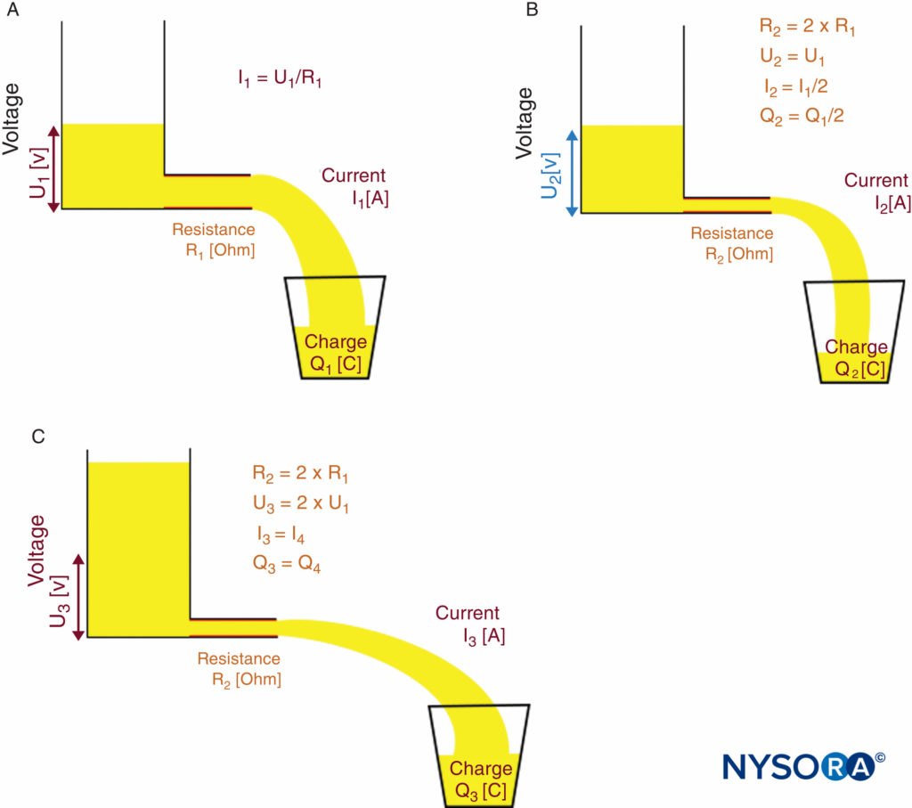
FIGURE 10. Ohm’s law and principle of a constant-current source. Functional principle of a constant-current source. A: Low-resistance R1 requires voltage U1 to achieve desired current I1.B: High-resistance R2 = 2 × R1 causes current I to decrease to I2 = I1/2 if voltage U remains constant (U2 = U1). C: Constant-current source automatically increases output voltage to U3 = 2 × U1 to compensate for the higher-resistance R2; therefore, current I increases to the desired level of I3 = I1
Coulomb’s Law, Electric Field, Current Density, and Charge
According to Coulomb’s law, the strength of the electric field, and therefore the corresponding current density J, in relation to the distance from the current source is given by where k is a constant, and I0 is the initial current. This means that the current (or charge) that reaches the nerve decreases by a factor of 4 if the distance to the nerve is doubled, or con-versely, it increases by a factor of 4 if the distance is divided in half (ideal conditions assumed).
![]()
The charge Q is the product of current multiplied by time and is given in ampere-seconds (As) or coulombs (C). As an example, rechargeable batteries often have an indication of Ah or mAh as the measure of their capacitance of charge (kilo = 1000 or 103; milli = 0.001 or 10–3; micro = 0.000001 or 10–6; nano = 0.000000001 or 10–9).
Energy of Electrical Impulses Delivered by Nerve Stimulators and Related Temperature Effects
According to a worst-case scenario calculation, the temperature increase caused by a stimulus of 5-mA current and 1-ms dura-tion at a maximum output voltage of 95 V would be less than 0.5 C if all the energy were concentrated within a small volume of only 1 mm3 and no temperature dissipation into the sur-rounding tissue occurred. This calculation can be applied for the tip of a nerve stimulation needle.
The maximum energy E of the electrical impulse delivered by a common nerve stimulator would be
E ≤ U × I × t = 95 V × 5 mA × 1 ms = 0.475 mWs = 0.475 mJ
The caloric equivalent for water is cw = 4.19 J g–1 K–1.
One stimulus creates a temperature difference DT within 1 mm3 of tissue around the tip of a nerve stimulation needle. For the calculation that follows, it is assumed that tissue contains a minimum of 50% water, and the mass M of 1 mm3 of tissue is 1 mg.
DT ≤ 2 × E/(M × cw) = 2 × 0.475 × 10–3 J/(10–3 g × 4.19 g/K) = 0.45 K
That is, the maximum temperature increase in this worst-case scenario calculation is less than 0.5 C. In practice, this means that the temperature effect of normal nerve stimulation on the tissue can be neglected.


