Ultrasound has been used to image the human body for over half a century. Dr. Karl Theo Dussik, an Austrian neurologist, was the first to apply ultrasound as a medical diagnostic tool to image the brain [1]. Today, ultrasound (US) is one of the most widely used imaging technologies in medicine. It is portable, free of radiation risk, and relatively inexpensive when compared with other imaging modalities, such as magnetic resonance and computed tomography. Furthermore, US images are tomographic, i.e., offering a “cross-sectional” view of anatomical structures. The images can be acquired in “real-time,” thus providing instantaneous visual guidance for many interventional procedures including those for regional anesthesia and pain management. In this chapter, we describe some of the fundamental principles and physics underlying US technology that are relevant to the pain practitioner.
1. BASIC PRINCIPLES OF B-MODE US
Modern medical US is performed primarily using a pulse-echo approach with a brightness-mode (B-mode) display. The basic principles of B-mode imaging are much the same today as they were several decades ago. This involves transmitting small pulses of ultrasound echo from a transducer into the body. As the ultrasound waves penetrate body tissues of different acoustic impedances along the path of transmission, some is reflected back to the transducer (echo signals), and some continue to penetrate deeper. The echo signals returned from many sequential coplanar pulses are processed and combined to generate an image. Thus, an ultrasound transducer works both as a speaker (generating sound waves) and a microphone (receiving sound waves). The ultrasound pulse is in fact quite short, but since it traverses in a straight path, it is often referred to as an ultrasound beam. The direction of ultrasound propagation along the beamline is called the axial direction, and the direction in the image plane perpendicular to axial is called the lateral direction [2]. Usually, only a small fraction of the ultrasound pulse returns as a reflected echo after reaching a body tissue interface, while the remainder of the pulse continues along the beamline to greater tissue depths.
2. GENERATION OF ULTRASOUND PULSES
Ultrasound transducers (or probes) contain multiple piezoelectric crystals which are interconnected electronically and vibrate in response to an applied electric current. This phenomenon called the piezoelectric effect was originally described by the Curie brothers in 1880 when they subjected a cut piece of quartz to mechanical stress generating an electric charge on the surface [3]. Later, they also demonstrated the reverse piezoelectric effect, i.e., electricity application to the quartz resulting in quartz vibration [4]. These vibrating mechanical sound waves create alternating areas of compression and rarefaction when propagating through body tissues. Sound waves can be described in terms of their frequency (measured in cycles per second or hertz), wavelength (measured in millimeter), and amplitude (measured in decibel).
3. ULTRASOUND WAVELENGTH AND FREQUENCY
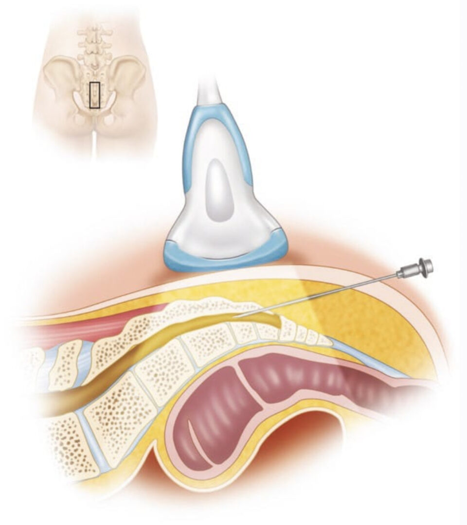
The wavelength and frequency of US are inversely related, i.e., ultrasound of high frequency has a short wavelength and vice versa. US waves have frequencies that exceed the upper limit for audible human hearing, i.e., greater than 20 kHz [3]. Medical ultrasound devices use sound waves in the range of 1–20 MHz. Proper selection of transducer frequency is an important concept for providing optimal image resolution in diagnostic and procedural US. High-frequency ultrasound waves (short wavelength) generate images of high axial resolution. Increasing the number of waves of compression and rarefaction for a given distance can more accurately discriminate between two separate structures along the axial plane of wave propagation. However, high-frequency waves are more attenuated than lower frequency waves for a given distance; thus, they are suitable for imaging mainly superficial structures [5]. Conversely, low-frequency waves (long wavelength) offer images of lower resolution but can penetrate to deeper structures due to a lower degree of attenuation (Fig. 1). For this reason, it is best to use high-frequency transducers (up to 10–15 MHz range) to image superficial structures (such as for stellate ganglion blocks) and low-frequency transducers (typically 2–5 MHz) for imaging the lumbar neuraxial structures that are deep in most adults (Fig. 2).
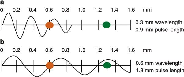
Fig. 1 Attenuation of ultrasound waves and their relationship to wave frequency. Note that higher frequency waves are more highly attenuated than lower frequency waves for a given distance. (a) Shorter wavelength with greater attenuation. (b) Longer wavelength with lesser attenuation (Reproduced with permission from Ref. [6])
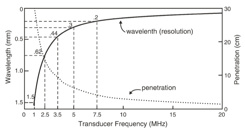
Fig. 2 A comparison of the resolution and penetration of different ultrasound transducer frequencies. (This figure was published in Ref. [3]. Copyright Elsevier (2000))
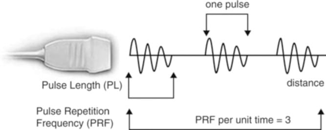
Fig. 3 Schematic representation of ultrasound pulse generation. (Reproduced with permission from Ref. [6])
4. ULTRASOUND-TISSUE INTERACTION
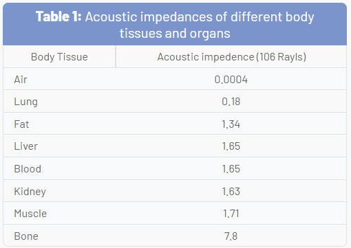
As US waves travel through tissues, they are partly transmitted to deeper structures, partly reflected back to the transducer as echoes, partly scattered, and partly transformed to heat. For imaging purposes, we are mostly interested in the echoes reflected back to the transducer. The amount of echo returned after hitting a tissue interface is determined by a tissue property called acoustic impedance. This is an intrinsic physical property of a medium defined as the density of the medium times the velocity of US wave propagation in the medium. Air-containing organs (such as the lung) have the lowest acoustic impedance, while dense organs such as bone have a very high-acoustic impedance (Table 1). The intensity of a reflected echo is proportional to the difference (or mismatch) in acoustic impedances between two mediums. If two tissues have identical acoustic impedance, no echo is generated. Interfaces between soft tissues of similar acoustic impedances usually generate low-intensity echoes. Conversely, interfaces between soft tissue and bone or the lung generate very strong echoes due to a large acoustic impedance gradient [7].
When an incident ultrasound pulse encounters a large, smooth interface of two body tissues with different acoustic impedances, the sound energy is reflected back to the transducer. This type of reflection is called specular reflection, and the echo intensity generated is proportional to the acoustic impedance gradient between the two mediums (Fig. 4). A soft tissue-needle interface when a needle is inserted “in-plane” is a good example of specular reflection. If the incident US beam reaches the linear interface at 90°, almost all of the generated echo will travel back to the transducer. However, if the angle of incidence with the specular boundary is less than 90°, the echo will not return to the transducer but rather be reflected at an angle equal to the angle of incidence (just like visible light reflecting in a mirror). The returning echo will potentially miss the transducer and not be detected. This is of practical importance for the pain physician and explains why it may be difficult to image a needle that is inserted at a very steep direction to reach deeply located structures.
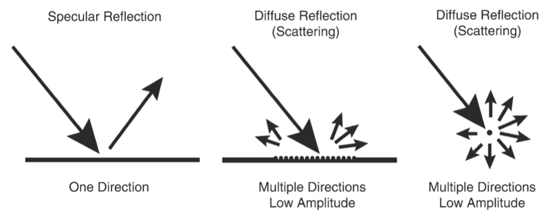
Fig. 4 Different types of ultrasound wave-tissue interactions. (Reproduced with permission from Ref. [6])
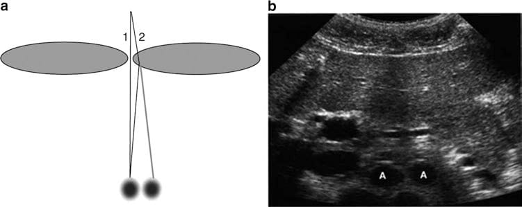
Fig. 5 Refraction artifact. Diagram (a) shows how sound beam refraction results in duplication artifacts. (b) is a transverse midline view of the upper abdomen showing duplication of the aorta (A) secondary to rectus muscle refraction. (This figure was published in Ref. [8]. Copyright Elsevier (2004))
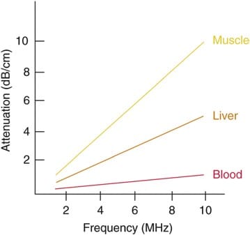
Fig. 6 Degrees of attenuation of ultrasound beams as a function of the wave frequency in different body tissues. (Reproduced with permission from Ref. [6])
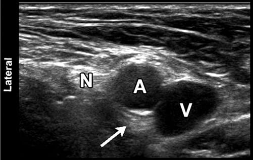
Fig. 7 Sonographic image of the femoral neurovascular structures in the inguinal area. A hyperechoic area can be appreciated deep into the femoral artery (arrowhead). This well-known artifact (known as posterior acoustic enhancement) is typically seen deep in fluid-containing structures. N femoral nerve; A, femoral artery; V, femoral vein
5. RECENT INNOVATIONS IN B – MODE ULTRASOUND
Some recent innovations that have become available in most ultrasound units over the past decade or so have significantly improved image resolution. Two good examples of these are tissue harmonic imaging and spatial compound imaging.
The benefits of tissue harmonic imaging were first observed in work geared toward imaging of US contrast materials. The term harmonic refers to frequencies that are integral multiples of the frequency of the transmitted pulse (which is also called the fundamental frequency or first harmonic) [9]. The second harmonic has a frequency of twice the fundamental. As an ultrasound pulse travels through tissues, the shape of the original wave is distorted from a perfect sinusoid to a “sharper,” more peaked, saw- tooth shape. This distorted wave in turn generates reflected echoes of several different frequencies of many higher-order harmonics. Modern ultrasound units use not only a fundamental frequency but also its second harmonic component. This often results in the reduction of artifacts and clutter in the near-surface tissues. Harmonic imaging is considered to be most useful in “technically difficult” patients with thick and complicated body wall structures.
Spatial compound imaging (or multibeam imaging) refers to the electronic steering of ultrasound beams from an array transducer to image the same tissue multiple times by using parallel beams oriented along with different directions [10]. The echoes from these different directions are then averaged together (compounded) into a single composite image. The use of multiple beams results in an averaging out of speckles, making the image look less “grainy” and increasing the lateral resolution. Spatial compound images often show reduced levels of “noise” and “clutter” as well as improved contrast and margin definition. Because multiple ultrasound beams are used to interrogate the same tissue region, more time is required for data acquisition and the compound imaging frame rate is generally reduced compared with that of conventional B-mode imaging.
6. CONCLUSION
US is relatively inexpensive, portable, safe, and real time in nature. These characteristics and continued improvements in image quality and resolution have expanded the use of US to many areas in medicine beyond traditional diagnostic imaging applications. In particular, its use to assist or guide interventional procedures is growing. Regional anesthesia and pain medicine procedures are some of the areas of current growth. Modern US equipment is based on many of the same fundamental principles employed in the initial devices used over 50 years ago. The understanding of these basic physical principles can help the anesthesiologist and pain practitioner better understand this new tool and use it to its full potential.