 Nerve Blocks App
 Pain Medicine Assistant App
 POCUS App
 IV Access App
 MSK Knee App
 VetRA App
 Nerve Block Manual
 Regional Anesthesia Updates
 Anesthesiology Manual
 Anesthesiology Review
 Anesthesia Updates 2025
 Anesthesia Updates 2026
 Pediatric Anesthesia Updates
 Airway Management Updates
 US Interventional Pain Manual
 Pain Medicine Updates
 Mastering Difficult IV Access
 PACU Nursing Manual
 RA Veterinary Manual
 About
About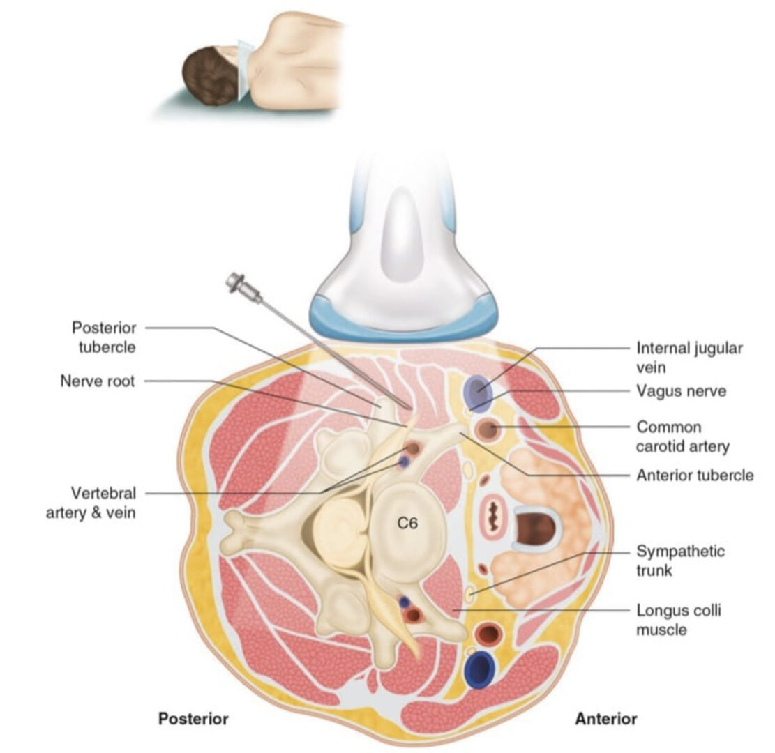
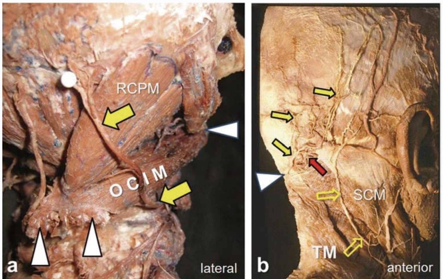
Anatomy of Cervical Nerve Root The cervical spinal nerve occupies the lower part of the foramen with the periradicular veins in the upper part. The radicular arteries arising from the vertebral, ascending cervical, and deep cervical arteries lie in close approximation to the spinal nerve. Huntoon showed in cadavers that the ascending and deep cervical arteries may contribute to the anterior spinal artery along with the vertebral artery. Twenty percent of the foramina dissected had the ascending cervical artery or deep cervical artery branches within 2 mm of the needle path for a cervical transforaminal procedure. One third of these vessels entered the foramen posteriorly, potentially forming a radicular or a segmental feeder vessel to the spinal cord, thereby making it vulnerable to inadvertent injury or injection even during correct needle placement. In a single cadaver study, Hoeft and coworkers showed that radicular artery branches from the vertebral artery lie over the most anteromedial aspect of the foramen; however those that arise from the ascending or deep cervical arteries are of greatest clinical significance because they must course medially throughout the entire length of the foramen.
1. INDICATIONS
Cervical nerve root block or transforaminal epidural injection is indicated in cervical radicular pain that is not responsive to conservative therapy. Cervical epidural injections can be performed using an interlaminar or a transforaminal approach. Since cervical radicular pain is frequently caused by foraminal stenosis, the transforaminal approach can maximize the concentration of steroid delivered to the affected nerve roots while reducing the volume of injectate required; this approach has been shown to be effective in relieving radicular symptoms.
2. LIMITATIONS OF THE FLUOROSCOPY-GUIDED TECHNIQUES
Cervical transforaminal injections have been traditionally performed with the use of fluoroscopy or computed tomography (CT). However, there have been few reports of fatal complications in the literature as a result of vertebral artery injury and/or infarction of the spinal cord and the brainstem. The mechanism of injury was hypothesized to be vasospasm or the particulate nature of the steroid injectate with embolus formation after inadvertent intraarterial injection.
Currently, the guidelines for cervical transforaminal injection technique involve introducing the needle under fluoroscopic guidance into the posterior aspect of the intervertebral foramen just anterior to the superior articular process in the oblique view to minimize the risk of injury to the vertebral artery or the nerve root. Despite strict adherence to these guidelines, adverse outcomes have been reported. A potential shortcoming of the described fluoroscopy-guided procedure is that the needle may puncture a critical contributing vessel to the anterior spinal artery in the posterior aspect of the intervertebral foramen. Here ultrasonography may come to play because it allows for visualization of soft tissues, nerves, and vessels and the spread of the injectate around the nerve; thus it may be potentially advantageous to fluoroscopy.
Ultrasound (US) allows real-time identification of the vessels before needle puncture. This is the most distinct advantage over fluoroscopic guidance, in which this complication can be recognized only after aberrant vascular uptake is noted with contrast agent injection. In other words, US can “prevent” intravascular penetration, while contrast fluoroscopy can “detect” intravascular injection after the fact.
3. LITERATURE REVIEW AND ADVANTAGES OF ULTRASOUND-GUIDED CERVICAL NERVE ROOT BLOCK
Extraforaminal “Periradicular” Versus Transforaminal Spread
It is very important to identify the target in the US-guided technique. The target is the nerve root, or more specifically the ventral ramus, in the transverse process groove between the anterior and posterior tubercles. Thus with US, the procedure is an extraforaminal selective nerve root block. This is contrary to the fluoroscopy-guided technique, in which the procedure is intended to be a transforaminal epidural injection.
As we described before, with a US approach, the needle is intentionally placed extraforaminally to avoid the vascularity within the foramen. Accordingly, it is not feasible to monitor the spread of the injectate through the foramen into the anterior epidural space because of the bony artifact of the transverse process. We, therefore, refer to this approach as a cervical selective nerve root block rather than cervical transforaminal epidural injection.
Yamauchi and colleagues monitored the efficacy and the spread of injectate in US-guided cervical nerve root block in a clinical study as well as a cadaveric study.
All target nerve roots in the 12 patients and 10 cadavers were correctly identified by US. This study suggested that there is no difference in the analgesic effects after US-guided injections, although the injectate spread tends to be mainly extraforaminal compared with the conventional transforaminal fluoroscopic technique.
Lee and coworkers compared the technical differences and clinical outcomes between US-guided cervical periradicular steroid injection (US-CPSI) and conventional fluoroscopy-guided transforaminal epidural injection. Their data suggested that US-CPSI can provide an adequate local spread pattern and tissue penetration for the treatment of cervical radicular pain.
4. IDENTIFICATION OF SMALL CRITICAL VESSELS
Narouze and associates reported a pilot study of ten patients who received cervical nerve root injections using US as the primary imaging tool with fluoroscopy as the control tool. In four patients they were able to identify vessels at the anterior aspect of the foramen, while two patients had critical vessels at the posterior aspect of the foramen. Further, in one patient this artery continued medially into the foramen, most likely forming or joining a segmental feeder artery. In these two cases, such vessels could have been injured easily in the pathway of a correctly placed needle with fluoroscopy.
Jee and coworkers evaluated the efficacy and safety of US-guided cervical nerve root block in comparison to fluoroscopy-guided injection in a prospective randomized, blinded, clinical trial (RCT). A total of 120 patients were randomly assigned to either fluoroscopy or US. The treatment effects and functional improvement after the nerve root block were compared at 2 and 12 weeks. There was no statistical difference between the two groups.
The authors in this study reproduced the findings by Narouze and colleagues but in a larger cohort of patients. In 21 patients in the US group, vessels were identified at the anterior aspect of the foramen. Eleven patients had a critical vessel at the posterior aspect of the foramen, and five patients had an artery continued medially into the foramen. On the other hand, five cases of intravascular injections were observed in the fluoroscopy group.
Obernauer and group also evaluated the accuracy, time-saving, radiation doses, safety, and pain relief after US-guided versus CT-guided cervical nerve root injections in a prospective randomized clinical trial (RCT). The accuracy of US-guided injections was 100%. The mean time to final needle placement in the US group was 2:21 ± 1:43 min versus 10:33 ± 02:30 min in the CT group. Both groups showed the same significant improvement in the visual analog scale.
5. WHY ULTRASOUND?
• Radiation-free imaging – This is especially important with cervical injections in which there are increased scattered radiations from the C-arm.
• Short procedure time compared to CT – Fluoroscopy time was reported to be significantly increased when a vascular injection was identified.
• Ability to identify and avoid vessels in the trajectory of the needle.
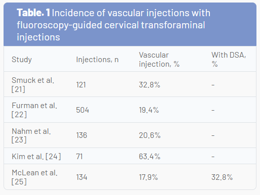
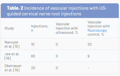
The incidence of vascular injection in fluoroscopy-guided CTFIs is significantly high (Table 1). This has led some to question the safety of the procedure. However, the incidence of vascular injections in the reported US-guided cervical nerve root injection studies was 0% (Table 2).
US is an excellent tool in visualizing and hence avoiding vascular injury during cervical spine procedures, while contrast fluoroscopy can only detect that the tip of the needle is intravascular. One should be mindful that fluoroscopy may not detect that the needle has already traversed a vessel on its way to the target, while US may help avoid this complication. US offers dynamic real-time imaging of the cervical spine, thereby avoiding the need to continuously adjust the C-arm to obtain a true lateral or an oblique foraminal view of the cervical spine.
Pearls for Improving the Safety for Cervical Nerve Root Injection
• Real-time contrast fluoroscopy
• Digital subtraction angiography (whenever available)
• US guidance • Blunt tip needle
• Test dose
• Diagnostic block with LA only
• Therapeutic block with nonparticulate steroids
6. SONOANATOMY OF THE CERVICAL SPINE AND IDENTIFICATION OF THE CERVICAL LEVEL
With patients lying in the lateral decubitus position, US examination is performed using a high-resolution linear array transducer. The transducer is applied transversely to the lateral aspect of the neck to obtain a short-axis view of the cervical spine (Fig.1).
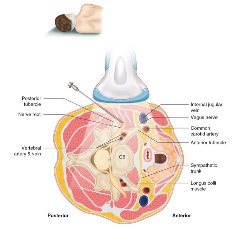
Fig.1 The orientation of the US transducer to obtain a short-axis view at C6 level is shown. (Reprinted with permission, Cleveland Clinic Center for Medical Art & Photography© 2008–2010. All rights reserved)
One can easily identify the cervical transverse process with the anterior and posterior tubercles as hyperechoic structures, the “two-humped camel” sign, and the hypoechoic round-to-oval nerve root in between (Fig. 2).

Fig.2 Short-axis transverse US images showing the anterior tubercle (at) and the posterior tubercle (pt) of the C5 transverse process as the two-humped camel sign. N nerve root, CA carotid artery. Solid arrows are pointing to the needle in place at the posterior aspect of the intervertebral foramen
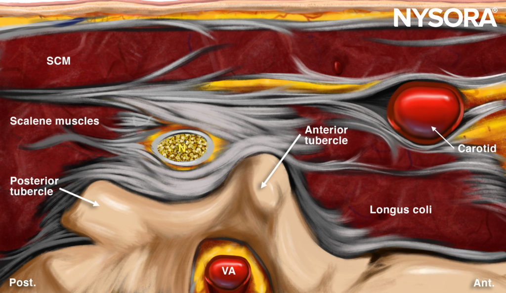
Reverse Ultrasound Anatomy illustration of figure 2. SCM, sternocleidomastoid muscle; N, nerve root; VA, vertebral artery.
First, the cervical level is determined by identifying the transverse process of the seventh and sixth cervical vertebrae (C7 and C6.) The seventh cervical transverse process (C7) differs from the above levels because it usually has a rudimentary anterior tubercle and one prominent posterior tubercle (Fig. 3).
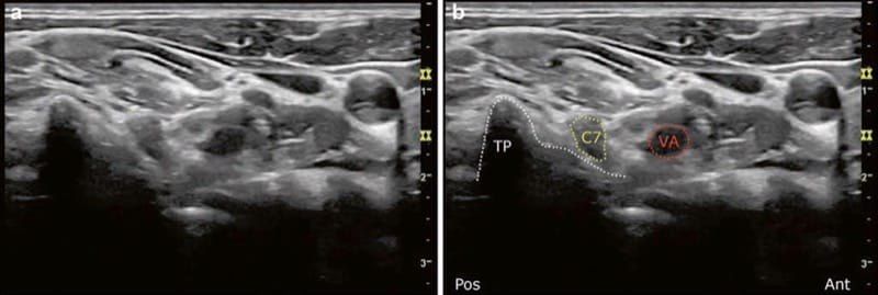
Fig.3 (a, b) Short-axis transverse US image showing the pt of the C7 transverse process. Note that the vertebral artery (VA) is anterior to the C7 nerve root. No anterior tubercle. (Reprinted with permission from Ohio Pain and Headache Institute)
By moving the transducer cranially, the transverse process of the sixth cervical spine comes into the image with the characteristic sharp anterior tubercle (Fig.4), after which the consecutive cervical spinal level can easily be identified.
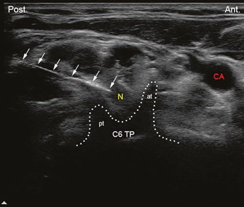
Fig.4 Short-axis transverse US image showing the sharp anterior tubercle (at) of the C6 transverse process (C6tp). N nerve root, CA carotid artery, pt posterior tubercle. Solid arrows are pointing to the needle in place at the posterior aspect of the intervertebral foramen
At higher levels than C6, the anterior tubercle becomes shorter and equal to the posterior tubercle with a shallow groove in between (see Fig.2). Another way to determine the cervical spinal level is by following the vertebral artery, which runs anteriorly at the C7 level (see Fig.3) before it enters the foramen of the C6 transverse process in about 90% of cases. However, it enters at C5 or higher in about 10% of cases (Fig. 5).
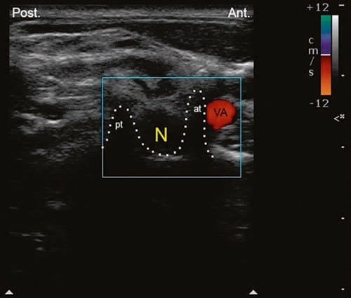
Fig.5 Short-axis transverse US image showing the sharp anterior tubercle (at) of the C6 transverse process; the vertebral artery (VA) is anterior. N nerve root, CA carotid artery, pt posterior tubercle
7. ULTRASOUND-GUIDED TECHNIQUE FOR CERVICAL SELECTIVE NERVE ROOT BLOCK
Once the appropriate spinal level is identified, a 22-gauge blunt tip needle can be introduced under real-time US guidance from posterior to anterior with an in-plane technique to target the corresponding cervical nerve root (from C3 to C8) at the external foraminal opening between the anterior and posterior tubercles of the transverse process (see Fig.2). The spread of the injectate around the cervical nerve can successfully be monitored with real-time US, and the absence of such spread around the nerve root may suggest unsuspected or inadvertent intravascular injection. However, it is difficult to monitor the spread of the injectate through the foramen into the epidural space because of the bony dropout artifact of the transverse process. We therefore refer to this approach as a cervical selective nerve root block rather than a cervical transforaminal epidural injection.
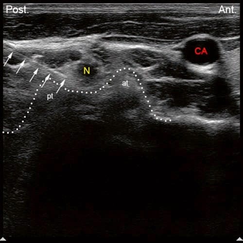
Fig.2 Short-axis transverse US images showing the anterior tubercle (at) and the posterior tubercle (pt) of the C5 transverse process as the two-humped camel sign. N nerve root, CA carotid artery. Solid arrows are pointing to the needle in place at the posterior aspect of the intervertebral foramen
The author believes that visualization of such small vessels (radicular arteries) may be very challenging and requires special training and expertise. Real-time fluoroscopy with contrast injection and digital subtraction when available should still be used with US as an adjunct to help identify blood vessels in the vicinity of the foramen (Figs.6, 7, and 8).
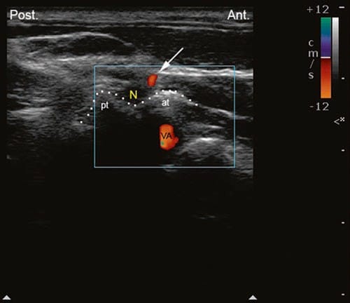
Fig.6 Short-axis transverse US image with color Doppler showing a small artery at the anterior aspect of the intravertebral foramen. at ante-rior tubercle, pt posterior tubercle, VA vertebral artery. (Reprinted with permission from Ohio Pain and Headache Institute)
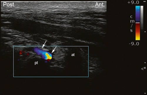
Fig.7 Short-axis transverse US image with color Doppler showing a small vessel at the posterior aspect of the intravertebral foramen. at anterior tubercle, pt posterior tubercle. (Reprinted with permission from Ohio Pain and Headache Institute)
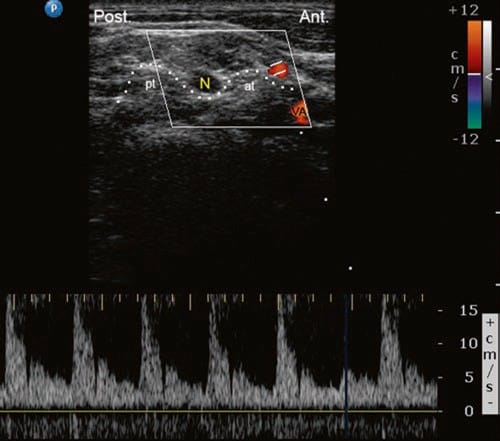
Fig.8 Short-axis transverse US image with pulsed-wave Doppler showing arterial perfusion in a small vessel at the anterior aspect of the intervertebral foramen. at anterior tubercle; N nerve root; pt posterior tubercle; VA vertebral artery
Clinical updates
- Yang et al. (Pain Ther, 2022) provide a narrative review of cervical selective nerve root block (SNRB) techniques for cervical spondylotic radiculopathy, classifying four main approaches: anterolateral, lateral, posterolateral (with a defined posterior-superior “safe zone”), and dorsal (direct and indirect), and detailing technical modifications to reduce neurovascular risk. They highlight that catastrophic complications (e.g., spinal cord or cerebral infarction) are strongly associated with inadvertent arterial injection of particulate steroids, recommending non-particulate agents (e.g., dexamethasone), routine contrast use (given up to 19% intravascular contrast uptake), careful preoperative vascular assessment (noting up to 29% vertebral artery variants near the foramen), and consideration of ultrasound guidance for real-time vascular visualization to improve safety.
Yang D, Xu L, Hu Y, Xu W. Diagnosis and Treatment of Cervical Spondylotic Radiculopathy Using Selective Nerve Root Block (SNRB): Where are We Now?. Pain Ther. 2022;11(2):341-357.