Central neuraxial blocks (CNBs; spinal and epidural) are techniques that are frequently used for anesthesia or analgesia in the perioperative period and for managing chronic pain. Success of these techniques depends on one’s ability to accurately locate the epidural or the intrathecal space. Traditionally, CNBs are performed using surface anatomical landmarks, fascial clicks, visualizing the free flow of cerebrospinal fluid (CSF) and “loss of resistance.” Although anatomical landmarks are useful, they are often difficult to locate or palpate in patients with obesity, edema in their backs, and underlying spinal deformity or after spinal surgery. Even in the absence of the above, a given intervertebral space is accurately identified in only 30% of cases, and anesthesiologists very frequently incorrectly identify a space higher than intended, which has been attributed as a cause for injury of the conus medullaris or spinal cord after spinal anesthesia. This error is exaggerated by obesity and as one tries to locate an intervertebral space in the upper spinal levels. Therefore, the Tuffier’s line, a surface anatomical landmark that is ubiquitously used during CNB, is not a reliable landmark. Moreover, because of the blind nature of the landmark-based techniques, it is not possible for the operator to predict the ease or difficulty of needle placement prior to skin puncture. Data from the United Kingdom indicate that 15% of spinal anesthetics are technically difficult, 10% require more than five attempts, and a failed CNB can occur in 5% of patients below the age of 50. Multiple attempts at needle placement can lead to pain and discomfort to the patient and injury to soft tissue structures that lie in the path of the advancing needle and may rarely result in complications, such as dural puncture, postdural puncture headache, or epidural hematoma. Therefore, any method that can reduce technical difficulties or assist the operator during CNB is desirable. Various imaging modalities (CT scan, MRI, and fluoroscopy) have been used to improve precision and accuracy during peripheral nerve block, chronic pain interventions, and lumbar puncture. However, this is not practical in the operating room environment because it involves transfer of the patient to the radiology suite, availability of a trained radiologist to interpret the images, and exposure to radiation and/or contrast medium with their attendant risks. Recent years have seen an increase in interest in the use of ultrasound (US) for interventions in regional anesthesia and pain medicine. There is evidence that peripheral nerve blocks that are performed with US, when compared with peripheral nerve stimulation, take less time to perform, require fewer needle passes, require less local anesthetic dosage, has a faster onset, produce superior quality of sensory block, last longer in duration, is less likely to fail, and also reduces inadvertent vascular puncture. When used for chronic pain interventions, US may eliminate or reduce exposure to radiation, something that may be welcomed by pain physicians. The US machine is gradually becoming an integral part of the armamentarium of an anesthesiologist, and an increasing number of peripheral nerve blocks are being performed with US assistance or real-time guidance. The same may also be true in pain medicine as pain physicians are embracing the US machine and performing pain interventions under ultrasound guidance or in conjunction with fluoroscopy. US may also offer other advantages when used for CNB. It is noninvasive, safe, and simple to use, can be quickly performed, does not involve exposure to radiation, provides real-time images, is free from adverse effects, and may also be beneficial in patients with abnormal or variant spinal anatomy. In this chapter, the author reviews our current understanding of spinal sonography and its applications for CNB.
1. HISTORY
Published literature suggests that Bogin and Stulin were the first to report the use of US for central neuraxial interventions. They used ultrasound to perform lumbar puncture and described their experience, in the Russian literature, in 1971. Porter et al. in 1978 used US to image the lumbar spine and measure the diameter of the spinal canal in diagnostic radiology. Cork et al. were the first group of anesthesiologists to use US to locate the landmarks relevant for epidural anesthesia. Despite the poor quality of the US images in 1980, Cork et al.’s report was able to define, although for the skeptic not very convincingly, the lamina, ligamentum flavum, transverse process, spinal canal, and vertebral body. Thereafter, US was used mostly to preview the spinal anatomy and measure the distances from the skin to the lamina and epidural space before epidural puncture. Grau et al. from Heidelberg in Germany conducted a series of investigations, between 2001 and 2004, to evaluate the utility of US for epidural access, which significantly improved our understanding of spinal sonography. Grau et al. also describe a two-operator technique of real-time US visualization, through a paramedian sagittal axis, of an advancing epidural needle that was inserted through the midline during a combined spinal epidural procedure. It appears that the quality of US imaging that was available at the time hindered widespread acceptance and further research in this area. Recent improvements in US technology allow us to image the spine and neuraxial structures with improved clarity, and the authors group from the Chinese University of Hong Kong has recently published their experience on real-time ultrasound-guided (USG) epidural access performed by a single operator.
2. ULTRASOUND IMAGING OF THE SPINE
Basic Considerations
The neuraxial structures are located at a depth that necessitates the use of low-frequency US (2–5 MHz) and curved array transducers for US imaging of the spine. Lowfrequency US provides good penetration but lacks spatial resolution at the depths (5–7 cm) at which the neuraxial structures are located. Nevertheless, high-frequency US has also been used to image the spine. Although highfrequency US provides better resolution than low-frequency US, it lacks penetration, which seriously limits its usage other than for imaging superficial structures of the spine. Moreover, the field of vision with a high-frequency linear transducers is also very limited compared to that of a low-frequency curved array transducer which produces a divergent beam with a wide field of vision. The latter is particularly useful during USG interventions of the spine (see below). Besides, the bony framework of the spine also does not lend to optimal conditions for US imaging of the neuraxial structures because it reflects majority of the incident US energy before it even reaches the spinal canal. Moreover, the acoustic shadow of the bony structures of the spine produces a narrow acoustic window for imaging. This often results in US images of variable quality. However, recent improvements in US technology, image processing capabilities of US machines, the availability of compound imaging, and the development of new scan protocols (see below) have significantly improved our ability to image the spine. Today it is possible to accurately identify the neuraxial anatomy relevant for CNB. Also of note is that technology that was once only available in the high-end cartbased US systems are now available in portable US devices making them adequate for spinal sonography and USG CNB.
3. AXIS OF SCAN
An US scan of the spine can be performed in the transverse (axial scan) or longitudinal (sagittal) axis with the patient in the sitting, lateral decubitus, or prone position. The sagittal scan is performed either through the midline (midline sagittal or median scan) or through a paramedian [paramedian sagittal scan (PMSS)] location. The prone position is useful in patients presenting for a chronic pain procedure when fluoroscopy may also be used in conjunction with US imaging. Since the bony framework of the spine wraps around the neuraxial structures, they can only be optimally visualized, within the spinal canal, if the US beam is insonated through the widest acoustic window available. Grau et al. have demonstrated that the PMSS plane is better than the median transverse or median sagittal plane for visualizing the neuraxial structures. There are also proponents of the transverse axis for US imaging the spine. In fact the two axis of scan complement each other during an US examination of the spine. In a recent investigation, the authors group objectively compared the visibility of neuraxial structures when the spine was imaged in the paramedian sagittal and paramedian oblique sagittal axis, i.e., with the transducer tilted slightly medially during the scan (Fig. 1). The medial tilt is done to ensure that the incident US beam enters the spinal canal through the widest part of the interlaminar space and not the lateral sulcus. Neuraxial structures were significantly better visualized in the PMOS scans (data to be published), and therefore the PMOS axis is the author’s preferred axis for imaging during USG CNB in the lumbar region (see below).
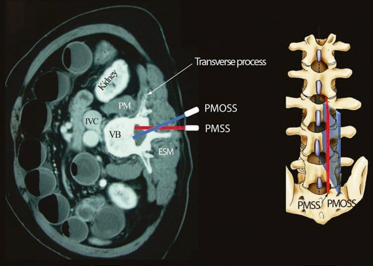
Fig.1 Paramedian sagittal scan of the lumbar spine. The paramedian sagittal axis of scan (PMSS) is represented by the red color, and the paramedian oblique sagittal axis of scan (PMOS) is represented by the blue color. Note how the PMOSS is tilted slightly medially. This is done to ensure that majority of the ultrasound energy enters the spinal canal through the widest part of the interlaminar space.
(Reproduced with permission from www.aic.cuhk.edu.hk/usgraweb)
Liberal amounts of US gel are applied to the skin over the area of interest prior to the scout (preview) scan for acoustic coupling. The objective of the scout scan is to preview the anatomy; optimize the image; identify any underlying asymptomatic abnormality or variation; measure relevant distances to the lamina, ligamentum flavum, or dura; and identify the best possible location and trajectory for needle insertion. The US image is optimized by making the following adjustments on the US unit: (a) selecting an appropriate preset (can be customized), (b) setting an appropriate scanning depth (6–10 cm) depending on the body habitus of the patient, (c) selecting the “general” optimization (midfrequency range) option of the broadband transducer, (d) adjusting the “focus” to a depth corresponding to the area of interest, and finally (e) manually adjusting the “gain,” “dynamic range,” and “compression” settings to obtain the best possible image. Compound imaging and selecting an appropriate “map” when available are also useful in improving the quality of the images. Once an optimal image is obtained, the position of the transducer is marked on the patients’ back using a skin marking pen to ensure that the transducer is returned to the same position after sterile preparations are made before the intervention. This also circumvents the need to repeat the scout scan routine to identify a given intervertebral space.
4. SPINAL SONOANATOMY
Currently, there are limited data on spinal sonography or on how to interpret US images of the spine. Even recent textbooks of regional anesthesia have very limited or no information on this subject. Moreover, while the landscape of regional anesthesia is changing and US guidance for peripheral nerve blocks is becoming an integral part of regional anesthetic practice, it may be fair to say that there are few anesthesiologists or pain physicians who currently use US for CNB. This is quite interesting when there is evidence to suggest that US improves technical and clinical outcomes during CNB, and emergency physicians are able to interpret US images of the spine and are performing lumbar puncture in the accident and emergency department using US. Even after the National Institute for Health and Care Excellence (NICE) in the United Kingdom (UK) recommended that ultrasound be used for epidural insertions, 97% of respondents to a survey in the United Kingdom had never used US to image the epidural space. The reason for this paucity of data or a lack of interest in the use of US for imaging the spine and performing central neuraxial interventions is not clear, but the author believes that it may be due to a lack of understanding of spinal sonoanatomy. Today there are models to learn musculoskeletal US imaging techniques (human volunteers), the sonoanatomy relevant for peripheral nerve blocks (human volunteers or cadavers), and the required interventional skills (tissue mimicking phantoms, fresh cadavers); however, when it comes to learning spinal sonoanatomy or the interventional skills required for USG CNBs, there are very few models or tools available today for this purpose.
5. THE WATER-BASED SPINE PHANTOM
Let us consider that the spine is made up of bone and soft tissue. If one is able to accurately identify the osseous elements of the spine, then one should be able to identify the gaps in the bony framework, i.e., the interlaminar space or the interspinous space, through which the US beam can be insonated to visualize the neuraxial structures within the spinal canal and/or insert a needle during US-assisted or US-guided CNB. The author and his group have recently described using a “water-based spine phantom” to study the osseous anatomy of the spine (Fig. 2a). This is based on a model previously described by Greher et al. to study the osseous anatomy relevant for USG lumbar facet nerve block. The “water-based spine phantom” is prepared by immersing a commercially available lumbosacral spine model (Sawbones, Pacific Research Laboratories, Inc.,Vashon, WA) in water (Fig. 2a) and scanning it in the transverse and sagittal axis through the water. We have found that each osseous element of the spine has a “signature” appearance (Figs. 2, 3, and 4) and they are comparable to that seen in vivo (Figs. 3 and 4). Being able to recognize these patterns is in the author’s opinion the first step toward learning how to interpret US images of the spine. Representative US images of the spinous process (Fig. 2b, c), L5/S1 interlaminar space or gap (Fig. 3a, b), lamina (Fig. 3c, d), articular process of the facet joint (Figs. 2d and 3a), and the transverse process (Fig. 4c) from the “water-based spine phantom” are presented in Figs. 2, 3, and 4. Another important feature of the phantom described above is that one is able to see through the water, so it is possible to validate the sonographic appearance of a target osseous structure by performing the scan with a marker (e.g., a needle) in contact with it.
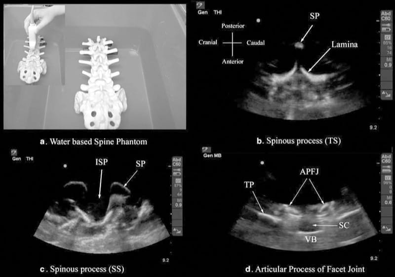
Fig.2 The water-based spine phantom (a) and sonograms of the spinous process in the transverse (b) and sagittal (c) axes and a scan through the interspinous space (d). SP spinous process, ISP interspi-nous space, TP transverse process, APFJ articular process of the facet joints, SC spinal canal, VB vertebral body, TS transverse scan, SS sagit-tal scan. (Reproduced with permission from www.aic.cuhk.edu.hk/usgraweb)

Fig.3 Paramedian sagittal sonogram of the L5/S1 interlaminar space or gap (a) and the lamina of the lumbar vertebra (c) from the water-based spine phantom and corresponding images from volunteers (b, d). Note the similarities in the sonographic appearances of the osseous elements in the phantom and volunteers. ESM erector spinae muscle, LF ligamentum flavum, PD posterior dura, CE cauda equina, ITS intrathecal space, ILS interlaminar space (Reproduced with permission from www.aic.cuhk.edu.hk/usgraweb)

Fig.4 Paramedian sagittal sonogram of the articular process of the facet joints (a) and transverse process (c) from the water-based spine phantom and corresponding images from volunteers (b, d). Once again note the similarities in the sonographic appearances of the osseous elements in the phantom and volunteers. APFJ articular process of the facet joints, TP transverse process, PM psoas major muscle. (Reproduced with permission from www.aic.cuhk.edu.hk/usgraweb)
6. ULTRASOUND IMAGING OF THE SACRUM
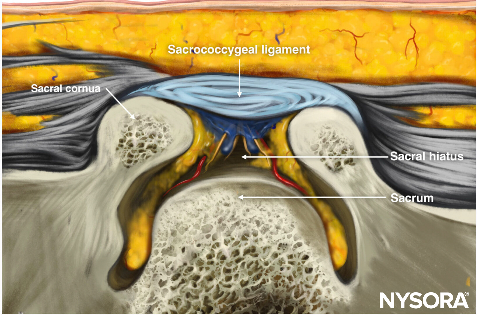
US imaging of the sacrum is usually performed to identify the sonoanatomy relevant for a caudal epidural injection. Since the sacrum is a superficial structure, a high-frequency linear array transducer is used for the scan. The patient is positioned in the lateral or prone position with a pillow under the abdomen to flex the lumbosacral spine. On a transverse sonogram of the sacrum at the level of the sacral hiatus, the sacral cornua are seen as two hyperechoic reversed U-shaped structures, one on either side of the midline (Fig. 5). Connecting the two sacral cornua and deep to the skin and subcutaneous tissue is a hyperechoic band, the sacrococcygeal ligament (Fig. 5). Anterior to the sacrococcygeal ligament is another hyperechoic linear structure, which represents the posterior surface of the sacrum (Fig. 5). The hypoechoic space between the sacrococcygeal ligament and the bony posterior surface of the sacrum is the sacral hiatus (Fig. 5). The two sacral cornua and the posterior surface of the sacrum produce a pattern on the sonogram that we refer to as the “frog eye sign” because of its resemblance to the eyes of a frog. On a sagittal sonogram of the sacrum at the level of the sacral cornua, the sacrococcygeal ligament, the base of sacrum, and the sacral hiatus are also clearly visualized (Fig. 6).
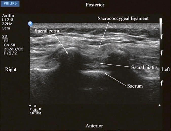
Fig.5 Transverse sonogram of the sacrum at the level of the sacral hiatus. Note the two sacral cornua and the hyperechoic sacrococcygeal ligament that extends between the two sacral cornua. The hypoechoic space between the sacrococcygeal ligament and the posterior surface of the sacrum is the sacral hiatus.
(Reproduced with permission from www.aic.cuhk.edu.hk/usgraweb)

Fig.6 Sagittal sonogram of the sacrum at the level of the sacral hiatus. Note the hyperechoic sacrococcygeal ligament which extends from the sacrum to the coccyx and the acoustic shadow of the sacrum which completely obscures the sacral canal.
(Reproduced with permission from www.aic.cuhk.edu.hk/usgraweb)
Above the sacral hiatus on a sagittal sonogram, the sacrum is identified as a flat hyperechoic structure with a large anterior acoustic shadow (Fig. 6). If one slides the transducer cephalad, maintaining the same orientation, a dip or gap is seen between the sacrum and the L5 lamina (PMSS), which is the L5/S1 intervertebral space and is also referred to as the L5/S1gap (Figs. 3a, b and 7). This is the sonographic landmark that is often used to identify a specific lumbar intervertebral space (L4/L5, L3/L4, etc.) by counting upward. US is more accurate than palpation in identifying a given lumbar intervertebral space. However, since US localization of the lumbar intervertebral spaces relies on one’s ability to locate the L5/ S1 gap on the sonogram, there are limitations of this method in the presence of a sacralized L5 vertebra or a lumbarized S1 vertebra when the L4/L5 interspace may be misinterpreted as the L5/S1 gap. Since it is not possible to predict the presence of the above without alternative imaging (x-ray, CT, or MRI), the L5/S1 gap is still a useful sonographic landmark when used for USG CNB, although one must bear in mind that occasionally the identified intervertebral level may be off by one or two intervertebral levels.
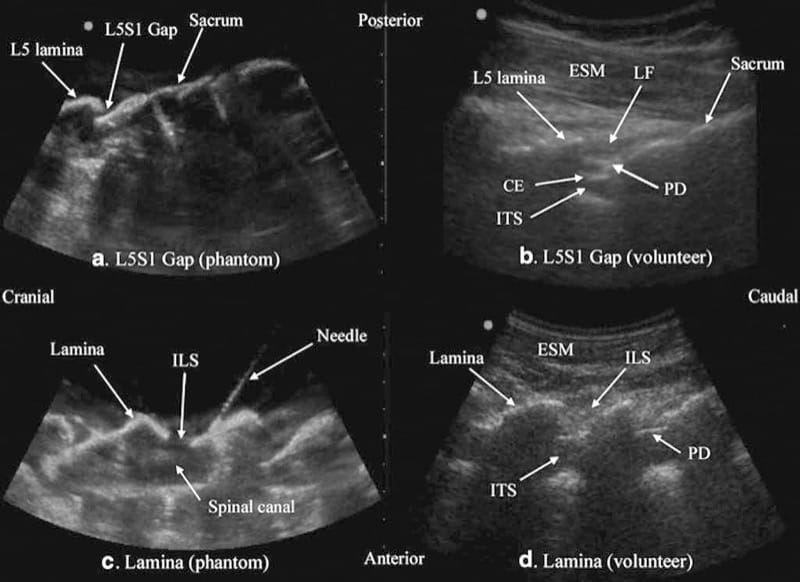
Fig.3 Paramedian sagittal sonogram of the L5/S1 interlaminar space or gap (a) and the lamina of the lumbar vertebra (c) from the water-based spine phantom and corresponding images from volunteers (b, d). Note the similarities in the sonographic appearances of the osseous elements in the phantom and volunteers. ESM erector spinae mus-cle, LF ligamentum flavum, PD posterior dura, CE cauda equina, ITS intrathecal space, ILS interlaminar space (Reproduced with permission from www.aic.cuhk.edu.hk/usgraweb)
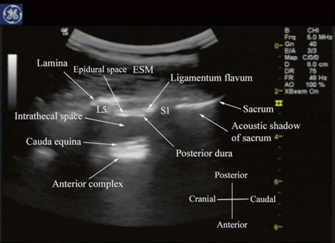
Fig.7 Paramedian sagittal sonogram of the lumbosacral junction. The posterior surface of the sacrum is identified as a flat hyperechoic surface with a large acoustic shadow anterior to it. The dip or gap between the sacrum and the lamina of L5 is the L5/S1 intervertebral space. ESM erector spinae muscle. (Reproduced with permission from www.aic.cuhk.edu.hk/usgraweb)
7. ULTRASOUND IMAGING OF THE LUMBAR SPINE
For a transverse scan of the lumbar spine, the US transducer is positioned over the spinous process with the patient in the sitting or lateral position. On a transverse sonogram, the spinous process is seen as a hyperechoic reflection under the skin and subcutaneous tissue, anterior to which there is a dark acoustic shadow that completely obscures the underlying spinal canal and thus the neuraxial structures (Fig. 8). Therefore, this view is not ideal for imaging the neuraxial structures but is useful for identifying the midline when the spinous processes cannot be palpated (obesity and in those with edema in their backs). If one now slides the transducer slightly cranially or caudally, it is possible to perform a transverse scan of the lumbar spine with the US beam being insonated through the interspinous space (interspinous view) (Fig. 9). Since the US signal is now not impeded by the spinous process, the ligamentum flavum, posterior dura, thecal sac, and the anterior complex (discussed below) are visualized in the midline (from a posterior to anterior direction) within the spinal canal, and laterally the articular process of the facet joints (APFJ) and the transverse processes are visible (Fig. 9). The resultant sonogram produces a pattern which Carvalho likens to a “flying bat.” The interspinous view can also be used to determine whether there is any rotation in the vertebra such as in scoliosis. Normally the APFJs on either side of the spine are symmetrically located (Fig. 9). However, if they are asymmetrically located or either one of the articular processes is not visible, then one should suspect rotation of the spine (provided the transducer is correctly positioned and aligned) as in scoliosis and anticipate a potentially difficult spinal or epidural.
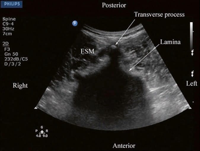
Fig.8 Transverse sonogram of the lumbar spine with the transducer positioned directly over the spinous process. Note the acoustic shadow of the spinous process which completely obscures the spinal canal and the neuraxial structures. ESM erector spinae muscle.
(Reproduced with permission from www.aic.cuhk.edu.hk/ usgraweb
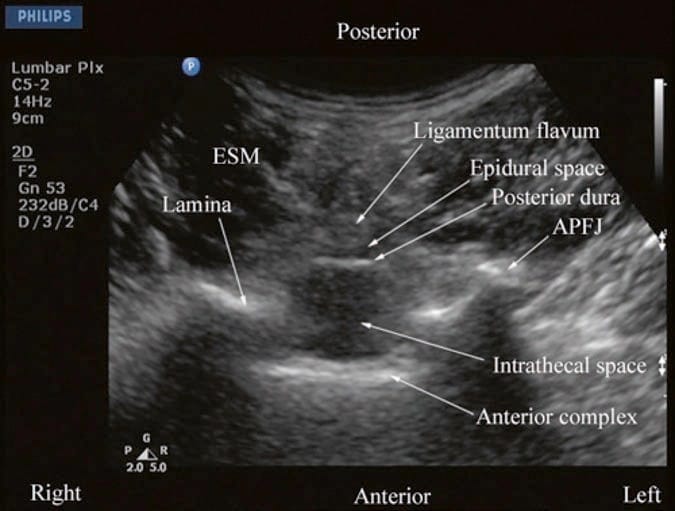
Fig.9 Transverse sonogram of the lumbar spine with the transducer positioned such that the ultrasound beam is insonated through the interspinous space. The ligamentum flavum, epidural space, posterior dura, intrathecal space, and anterior complex are now visible within the spinal canal in the midline and, the APFJ and the TP are visible laterally. Note how the articular processes of the facet joints (APFJ) on either side are symmetrically located. ESM erector spinae muscle. (Reproduced with permission from www.aic. cuhk.edu.hk/usgraweb)
For a sagittal scan of the lumbar spine, the author prefers to position the patient in the left lateral position with the knees and hip slightly flexed (Fig. 10). The transducer is positioned 1–2 cm lateral to the spinous process (midline) at the lower back on the nondependent side with its orientation marker directed cranially. The transducer is also tilted slightly medially during the scan so that the US beam is insonated in a PMOS plane (Fig. 10, inset). During the scout scan, the L3/L4 and L4/L5 interlaminar space is located as described above. On a PMOS sonogram of the lumbar spine, the erector spinae muscles are clearly delineated and lie superficial to the lamina. The lamina appears hyperechoic and is the first osseous structure visualized (Fig. 10). Since the bone impedes the passage of US, there is an acoustic shadow anterior to each lamina. The sonographic appearance of the lamina produces a pattern that resembles the head and neck of a horse which we refer to as the “horse head sign” (Figs. 3c, d and 10). The interlaminar space is the gap between the adjoining lamina. In contrast, the articular processes of the facet joints appear as one continuous hyperechoic wavy line with no intervening gaps as seen at the level of the lamina (Fig. 4a, b) and are the usual clues to differentiate the lamina from the articular processes. The APFJ in a sagittal sonogram produces a pattern that resembles multiple camel humps which we refer to as the “camel hump sign” (Fig. 4a, b). In between the dark acoustic shadows of adjacent lamina, there is a rectangular area in the sonogram where the neuraxial structures are visualized (Fig. 10). This is the “acoustic window” and results from reflections of the US signal from the neuraxial structures within the spinal canal. The ligamentum flavum is also hyperechoic and is often seen as a thick band across two adjacent laminae (Fig. 10). The posterior dura is the next hyperechoic structure anterior to the ligamentum flavum, and the epidural space is the hypoechoic area (few millimeters wide) between the ligamentum flavum and the posterior dura (Fig. 10). The thecal sac with the CSF is the anechoic space anterior to the posterior dura. The cauda equina, which is located within the thecal sac, is often seen as multiple horizontal hyperechoic shadows within the anechoic thecal sac (Fig. 10), and their location can vary with posture. Pulsations of the cauda equina are also identified in some patients. The anterior dura is also hyperechoic, but it is often difficult to differentiate it from the posterior longitudinal ligament and the vertebral body or the intervertebral disk as they are of the same echogenicity (isoechoic) and very closely opposed to each. This often results in a single, composite, hyperechoic reflection anteriorly that is also referred to as the “anterior complex” (Fig. 10).

Fig.3 Paramedian sagittal sonogram of the L5/S1 interlaminar space or gap (a) and the lamina of the lumbar vertebra (c) from the water-based spine phantom and corresponding images from volunteers (b, d). Note the similarities in the sonographic appearances of the osseous elements in the phantom and volunteers. ESM erector spinae mus-cle, LF ligamentum flavum, PD posterior dura, CE cauda equina, ITS intrathecal space, ILS interlaminar space (Reproduced with permission from www.aic.cuhk.edu.hk/usgraweb)
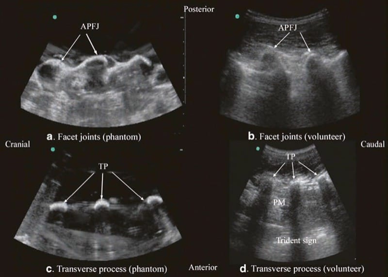
Fig.4 Paramedian sagittal sonogram of the articular process of the facet joints (a) and transverse process (c) from the water-based spine phantom and corresponding images from volunteers (b, d). Once again note the similarities in the sonographic appearances of the osseous elements in the phantom and volunteers. APFJ articular process of the facet joints, TP transverse process, PM psoas major muscle. (Reproduced with permission from www.aic.cuhk.edu.hk/usgraweb)
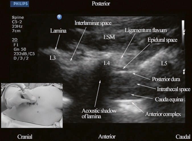
Fig.10 Paramedian oblique sagittal sonogram of the lumbar spine at the L3/L4 and L4/L5 level. Note the hypoechoic epidural space (few millimeters wide) between the hyperechoic ligamentum flavum and the posterior dura. The intrathecal space is the anechoic space between the posterior dura and the anterior complex in the sonogram. The cauda equina nerve fibers are also seen as hyperechoic, longitudinal structures within the thecal sac. Picture in the inset shows how the transducer is positioned on the nondependent side of the back and how it is tilted slightly medially during the scan. ESM erector spinae muscle, L3 lam-ina of L3 vertebra, L4 lamina of L4 vertebra, L5 lamina of L5 vertebra. (Reproduced with permission from www.aic.cuhk.edu.hk/usgraweb)
8. ULTRASOUND IMAGING OF THE THORACIC SPINE
US imaging of the thoracic spine is more demanding because of the acute angulation of the spinous processes and the narrow interspinous spaces. This results in a narrow acoustic window for US imaging with limited visibility of the neuraxial structures (Fig. 11). US imaging of the thoracic spine can be performed via the transverse (median transverse scan) or paramedian axis with the patient in the sitting or lateral decubitus position. Grau et al. performed US imaging of the thoracic spine at the T5/T6 level in young volunteers and compared these images with MRI images of the spine at the same level. They observed that the US scans in the transverse axis produced the best images of the neuraxial structures and the epidural space was best visualized in the paramedian scans. However, compared to the MRI images, which were easier to interpret, US had limited ability to delineate the epidural space or the spinal cord but was better than MRI in demonstrating the dura. As in the lumbar region, the lamina in the thoracic region is also hyperechoic, but the acoustic window for visualizing the neuraxial structures is very narrow (Fig. 11). Despite this, the posterior dura, which is also hyperechoic, is consistently visualized through the narrow interlaminar spaces, but the epidural space is more difficult to delineate (Fig. 11).
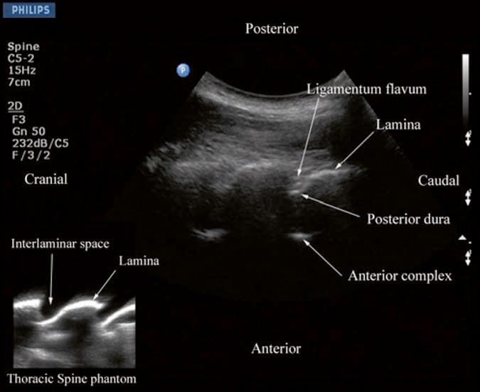
Fig.11 Paramedian oblique sagittal sonogram of the midthoracic spine. Note the narrow acoustic window through which the posterior dura and anterior complex are visible. Picture in the inset shows a sagittal sonogram of the thoracic spine from the water-based spine phantom. ILS interlaminar space.
(Reproduced with permission from www.aic.cuhk.edu.hk/usgraweb)
9. ULTRASOUND-GUIDED CNB
US is commonly used to preview the spinal anatomy prior to performing a traditional epidural access using “loss of resistance.” Real-time USG epidural access, as a two-operator or as a single-operator technique, has also been described in the literature. The patient can be positioned in the sitting, lateral, or prone position during a USG CNB. The author believes that for maximum manual dexterity, the patient should be positioned such that the operator can use the dominant hand to perform the intervention and use the nondominant hand to hold the US transducer and perform the scan. Although liberal amounts of US gel are used for acoustic coupling during the scout scan, it is the author’s practice not to apply US gel directly on to the patients’ skin over the area scanned during USG CNB. Normal saline solution, which is applied using sterile swabs, is used as an alternative coupling agent with the aim to keep the area under the footprint of the transducer moist. This is done because there are no data demonstrating the safety of US gel on the meninges or central neuraxial structures. Therefore, while preparing the US transducer, a thin layer of sterile US gel from a disposable sachet is applied directly on to the footprint of the transducer, which is then covered with a sterile-transparent dressing, making sure that no air is trapped between the footprint and the dressing.
The transducer and cable are then covered with a sterile plastic sleeve. Since no US gel is applied on the skin, as expected, there is a slight deterioration in the quality of the US image compared to that obtained during the scout scan, but this can be easily compensated by manually adjusting the overall gain and compression settings. All these additional steps bring about changes in our routine practice, which may increase the potential for infection via contamination during the preparation of the equipment. Therefore, strict asepsis must be maintained during any USG CNB.
10. CAUDAL EPIDURAL INJECTION
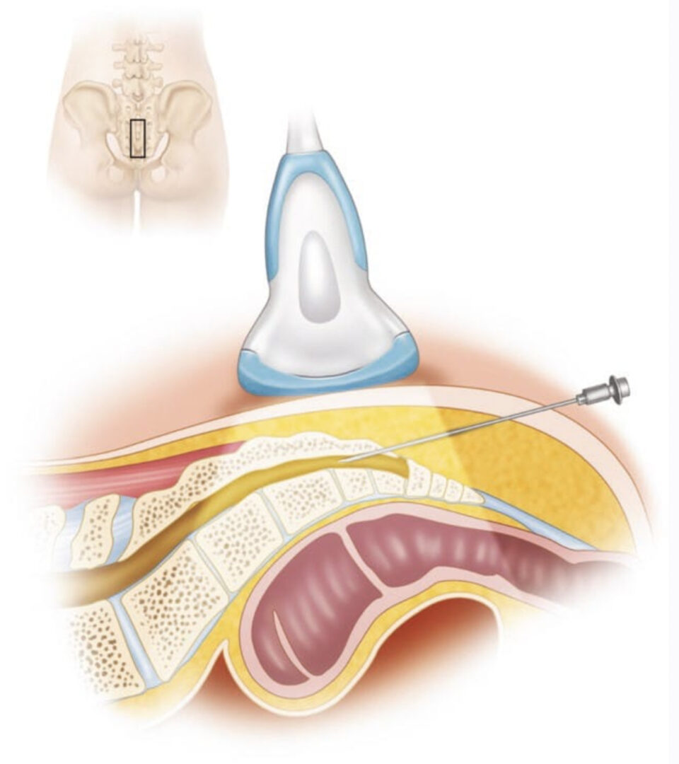
Caudal epidural injections (steroids or local anesthetics) are frequently performed for pain management. For a USG caudal epidural injection, a transverse or sagittal scan is performed at the level of the sacral hiatus. Since the sacral hiatus is a superficial structure, high-frequency (6–13 MHz) linear array transducer is commonly used for the scan as described above (Figs. 5 and 6). The block needle can be inserted in the short (out of plane) or long axis (in-plane) of the US plane. For a long-axis needle insertion (author’s preference), a sagittal scan is performed (Fig. 6), and the passage of the block needle through the sacrococcygeal ligament into the sacral canal is visualized in real time (Fig. 12). However, since the sacrum impedes the passage of the US beam, there is a large acoustic shadow anteriorly (Figs. 6 and 12), which makes it impossible to visualize the tip of the needle or the spread of the injectate within the sacral canal. Moreover an inadvertent intravascular injection, which is reported in 5–9% of such procedures, cannot be detected using US. So in clinical practice, one still has to rely on clinical signs such as the “pop” or “give” as the needle traverses the sacrococcygeal ligament, ease of injection, absence of subcutaneous swelling, “whoosh test,” nerve stimulation, or the assessment of the clinical effects of the injected drug to confirm correct needle placement. Chen et al. describe using fluoroscopy after contrast injection to confirm the position of a caudal needle that was placed under US guidance and report a 100% success rate. This is encouraging considering that even in experienced hands there is a failure to successfully place a needle in the caudal epidural space as high as 25%. More recently, Chen et al. have described US imaging as a screening tool for caudal epidural injections. In their cohort of patients, the mean diameter of the sacral canal at the sacral hiatus was 5.3 ± 2 mm, and the distance between the sacral cornua (bilateral) was 9.7 ± 1.9 mm. Chen et al. also identified that sonographic features such as a closed sacral hiatus and a sacral diameter of around 1.5 mm have a greater probability for a failed caudal epidural injection. Based on the published data, one can conclude that US, despite its limitation, may be useful as an adjunct tool for caudal epidural needle placement and has the potential to improve technical outcomes and minimize failure rates and exposure to radiation in the chronic pain setting and therefore deserves further investigation in the future.

Fig.5 Transverse sonogram of the sacrum at the level of the sacral hiatus. Note the two sacral cornua and the hyperechoic sacrococcygeal ligament that extends between the two sacral cornua. The hypoechoic space between the sacrococcygeal ligament and the posterior surface of the sacrum is the sacral hiatus. (Reproduced with permission from www.aic.cuhk.edu.hk/usgraweb)

Reverse Ultrasound Illustration of figure 5.
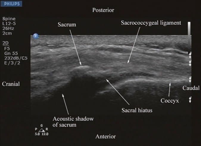
Fig.6 Sagittal sonogram of the sacrum at the level of the sacral hiatus. Note the hyperechoic sacrococcygeal ligament which extends from the sacrum to the coccyx and the acoustic shadow of the sacrum which completely obscures the sacral canal. (Reproduced with permission from www.aic.cuhk.edu.hk/usgraweb)
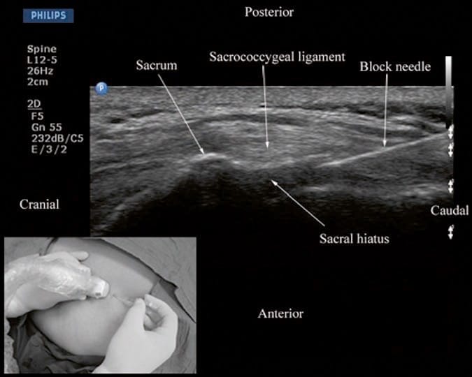
Fig.12 Sagittal sonogram of the sacrum at the level of the sacral hiatus during a real-time ultrasound-guided caudal epidural injection. Note the hyperechoic sacrococcygeal ligament and the block needle that has been inserted in the plane (in-plane) of the ultrasound beam. Picture in the inset shows the position and orientation of the transducer and the direction in which the block needle is inserted. (Reproduced with permission from www.aic. cuhk.edu.hk/usgraweb)
11. LUMBAR EPIDURAL INJECTION
During lumbar epidural access, US imaging can be used to preview the underlying spinal anatomy or to guide the needle in real time. As described above, realtime US guidance for epidural access is performed either as a two-operator or as a single-operator technique. In the former technique that was described by Grau et al. for combined spinal epidural anesthesia, the first operator performs the US scan via the paramedian axis, while the second operator performs the epidural access via the midline using the traditional “loss-of-resistance” technique. Grau et al. were able to visualize the advancing needle in all their cases despite the axis of the US scan and the needle insertion being different. Moreover, they were also able to visualize the dural puncture in all their patients and dural tenting in a few cases during the needle-through-needle spinal puncture. Recently, we have described the successful use of real-time US guidance in conjunction with loss of resistance to saline for paramedian epidural access, performed by a single operator, with the epidural needle inserted in the plane of the US beam. As a result, it is possible to visualize the advancing needle in real time until it is seen to engage in the ligamentum flavum (Fig. 13). We were able to circumvent the need for a second operator (additional hands), to perform the LOR, by using the Episure™ AutoDetect™ syringe (Indigo Orb, Inc., Irvine, CA), which is a new LOR syringe with an internal compression spring that applies constant pressure on the plunger (Fig. 14, inset). We were also able to demonstrate objective changes within the spinal canal, at the level of needle insertion, immediately after the loss of resistance to saline in majority (>50%) of our patients. Anterior displacement of the posterior dura and widening of the posterior epidural space were the most frequently visualized changes within the spinal canal, but compression of the thecal sac was also seen in a few patients (Fig.14). These are objective signs of a correct epidural injection and have previously been described in children. The neuraxial changes that occur within the spinal canal following the “loss of resistance” to saline may have clinical significance and are discussed in detail in our report. Despite our success with real-time USG epidural access, we have not been able to visualize an indwelling epidural catheter to date in adults. However, we have occasionally observed changes within the spinal canal, e.g., anterior displacement of the posterior dura and widening of the posterior epidural space, after an epidural bolus injection via the catheter. These are surrogate markers of the location of the catheter tip and of limited value in clinical practice. Our observations are in agreement with the experience of Grau and may be related to the small diameter and poor echogenicity of conventional epidural catheters that are in use today. There is a need to develop new epidural catheter designs with improved echogenicity.
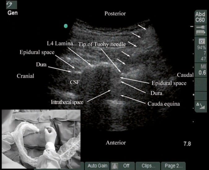
Fig.13 Paramedian oblique sagittal sonogram of the lumbar spine during real-time ultrasound-guided paramedian epidural access. The tip of the Tuohy needle (short white arrows) is seen embedded in the ligamentum flavum. Picture in the inset shows the position and orientation of the transducer and the direction in which the Tuohy needle is inserted (in-plane) during the epidural access. CSF cerebrospinal fluid. (Reproduced with permission from www.aic. cuhk.edu.hk/usgraweb)
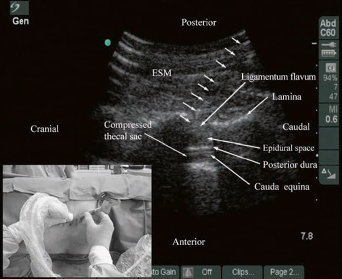
Fig.14 Paramedian oblique sagittal sonogram of the lumbar spine showing the sonographic changes within the spinal canal after the “loss of resistance” to saline. Note the anterior displacement of the posterior dura, widening of the posterior epidural space, and compression of the thecal sac. The cauda equina nerve roots are also now better visualized within the compressed thecal sac in this patient. Picture in the inset shows how the Episure™ AutoDetect™ syringe was used to circumvent the need for a third hand for the “loss of resistance.” (Reproduced with permission from www. aic.cuhk.edu.hk/usgraweb)
12. THORACIC EPIDURAL INJECTION
There are no published data on USG thoracic epidural blocks. This may be due to the poor US visibility of the neuraxial structures in the thoracic region (refer above) and the associated technical difficulties. However, despite the narrow acoustic window, the lamina, the interlaminar space, and the posterior dura are consistently visualized using the paramedian axis (Fig. 11). The epidural space is more difficult to delineate but is also best visualized in a paramedian scan (Fig. 11). As a result, the author has been using an US-assisted technique to perform thoracic epidural catheterization via the paramedian window. In this approach, the patient is positioned in the sitting position, and a paramedian oblique sagittal scan (PMOS) is performed at the desired thoracic level with the orientation marker of the transducer directed cranially (Fig. 15). Under strict aseptic precautions (described above), the Tuohy needle is inserted via the paramedian axis in real time and in the plane of the ultrasound beam (Fig. 15). The needle is steadily advanced until it is seen to contact the lamina or enter the interlaminar space. Since the lamina is relatively superficial in the thoracic region, it is possible to visualize the advancing Tuohy needle in real time (Fig. 15). Once the tip of the Tuohy needle is in contact with the lamina or in the interlaminar space, the author puts the US transducer down and uses the traditional loss-of-resistance to saline technique to access the epidural space. Preliminary experience with this approach indicates that US may improve the likelihood of thoracic epidural access on the first attempt. Research comparing the US-assisted technique described above with the traditional approach is planned at the author’s institution.

Fig.11 Paramedian oblique sagittal sonogram of the midthoracic spine. Note the narrow acoustic window through which the posterior dura and anterior complex are visible. Picture in the inset shows a sagittal sonogram of the thoracic spine from the water-based spine phantom. ILS interlaminar space.
(Reproduced with permission from www.aic.cuhk.edu.hk/usgraweb)
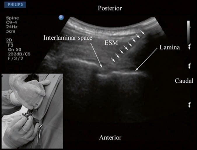
Fig.15 Paramedian oblique sagittal sonogram of the thoracic spine during an ultrasound-assisted paramedian epidural access. The Tuohy needle (short white arrows) has been inserted in the plane of the ultrasound beam, and its tip is seen in the interlaminar space. Picture in the inset shows the patient in the sitting position and how the transducer is positioned and oriented. Also note the direction in which the Tuohy needle is inserted (in-plane) during the paramedian epidural access. ESM erector spinae muscle. (Reproduced with permission from www.aic.cuhk.edu.hk/usgraweb)
13. SPINAL INJECTION
There are very limited data in the anesthesia or pain medicine literature on the use of US for spinal (intrathecal) injections although it has been shown to be useful for lumbar punctures by radiologists and emergency physicians. Majority of the data are in the form of case reports. Yeo and French, in 1999, were the first to describe the successful use of US to assist spinal injection in a patient with abnormal spinal anatomy. They used US to locate the vertebral midline in a parturient with severe scoliosis with Harrington rods in situ. Yamauchi et al. describe using US to preview the neuraxial anatomy and measure the distance from the skin to the dura in a postlaminectomy patient before the intrathecal injection was performed under x-ray guidance. Costello and Balki used US to facilitate spinal injection by locating the position of the L5/S1 space in a parturient with poliomyelitis and previous Harrington rod instrumentation of the spine. Prasad et al. report using US to assist spinal injection in a patient with obesity, scoliosis, and multiple previous back surgery with instrumentation. More recently, Chin et al. have described realtime ultrasound-guided spinal anesthesia in two patients with abnormal spinal anatomy (one had lumbar scoliosis, and the other had undergone spinal fusion surgery at the L23 level).
14. THE EVIDENCE
Currently, there are limited outcome data on the use of ultrasound for CNB. Majority of data are from its use in the lumbar region with limited data from the thoracic region. Most studies to date have evaluated the utility of performing a prepuncture US scan or scout scan. A scout scan allows one to identify the midline and accurately determine the interspace for needle insertion, which are useful in patients in whom anatomical landmarks are difficult to palpate, such as in those with obesity, edema in the back, or abnormal anatomy (scoliosis, postlaminectomy surgery, or spinal instrumentation). It also allows the operator to preview the neuraxial anatomy, identify asymptomatic spinal abnormalities such as in spina bifida, accurately predict the depth to the epidural space including in the obese patient, identify ligamentum defects, and determine the optimal site and trajectory for needle insertion. Cumulative evidence suggests that when an US examination is performed before the epidural puncture, it improves the success rate of epidural access on the first attempt, reduces the number of puncture attempts or the need to puncture multiple levels, and also improves patient comfort during the procedure. Preliminary data suggest that this may also be true in patients with presumed difficult epidural access such as in those with a history of difficult epidural access, obesity, and kyphosis or scoliosis of the lumbar spine. When used for obstetric epidural anesthesia, it also improves the quality of analgesia, reduces side effects, and improves patient satisfaction. There are also data demonstrating that a scout scan improves the learning curve of epidural blocks in parturients. Currently, there are very limited data evaluating real-time US guidance for epidural access, but preliminary results indicate that it also improves technical outcomes. Research in this area is ongoing at the author’s institution.
15. EDUCATION AND TRAINING
Learning USG CNB techniques takes time and patience. In the author’s experience, irrespective of the technique used, USG CNB and in particular real-time USG CNB are advanced techniques and by far the most difficult USG interventions. It also demands a high degree of manual dexterity, hand–eye coordination, and an ability to conceptualize 2D information into a 3D image. Therefore, before attempting to perform a USG CNB, the operator should have a sound knowledge of the basics of US, be familiar with spinal sonography and sonoanatomy, and have the necessary interventional skills. It is advisable to start by attending a course or workshop that is tailor-made for this purpose where one can learn the basic scanning techniques, spinal sonoanatomy, and the required interventional skills. Further experience of spinal sonography can also be acquired in volunteers. It appears that anesthesiologists with no prior experience in using US for CNB require more than the following: reading published educational material, attending a lecture and demonstration workshop, and performing 20 supervised scans to become competent in US assessment of the lumbar spine. Today there are very few models (phantoms) for practicing USG central neuraxial interventions. The authors group has been using anesthetized pigs and more recently a pig carcass model to acquire the skills necessary for USG central neuraxial interventions. Once the basic skills are attained, it is best to start by performing USG spinal injections, under supervision, before progressing on to performing epidurals. Real-time USG epidurals can be technically demanding even for an experienced operator. If there is no experience in USG CNB locally, then it is advisable to visit a center where such interventions are practiced. Today it is also not known how many such interventions need to be performed before one becomes proficient in performing realtime USG CNB. Further research in this area is warranted.
16. CONCLUSION
USG CNB is a promising alternative to traditional landmarkbased techniques. It is noninvasive, safe, and simple to use and can be quickly performed. It also does not involve exposure to radiation, provides real-time images, and is free from adverse effects. With recent improvements in ultrasound technology and image processing capabilities of US machines, today, it is possible to visualize neuraxial structures using US, and this has significantly improved our understanding of spinal sonoanatomy. US imaging has been used to assist or guide CNB in the sacral, lumbar, and thoracic regions. Majority of the outcome data are from its application in the lumbar region, and there are limited data on its use in the thoracic region. A prepuncture (scout) scan allows the operator to preview the spinal anatomy, identify the midline, accurately predict the depth to the epidural space, identify any rotational deformity in the spine, and determine the optimal site and trajectory for needle insertion. US imaging when used during CNB also improves the success rate of epidural access on the first attempt, reduces the number of puncture attempts or the need to puncture multiple levels, and also improves patient comfort during the procedure. The same may also apply in patients with presumed difficult epidural access and difficult spines. It is an excellent teaching tool for demonstrating the anatomy of the spine and improves the learning curve of epidural blocks in parturients. US also assists in performing CNB in patients who in the past may have been considered unsuitable for such procedures, e.g., in those with abnormal spinal anatomy. However, US guidance for CNB is still in its infancy, and evidence to support its use is sparse. There is also a paucity of data on the use of ultrasound for CNB in pain medicine. The author envisions that as ultrasound technology continues to improve and as more anesthesiologists and pain physicians embrace this technology and acquire the necessary skills to perform USG interventions, USG CNB will no doubt become more widespread and may become the standard of care in the future.
Clinical updates
Van den Broek et al. (Reg Anesth Pain Med, 2025) conducted a multicenter, randomized, open-label non-inferiority trial (n=90) comparing continuous erector spinae plane (ESP) block (0.125% bupivacaine at 5 mL/h with 3-hourly boluses) to thoracic epidural analgesia (TEA) after VATS, demonstrating non-inferior Quality of Recovery-15 scores on postoperative days 0–2. TEA provided lower pain scores at rest on POD 0 (median 1 vs. 3; P=0.01) and reduced rescue opioid use (0 mg vs. 8 mg on POD 1; P<0.001), but was associated with significantly higher rates of pruritus (37% vs. 2%) and urinary catheterization (70% vs. 21%). Overall length of stay and mobilization were similar, supporting continuous ESP as a less invasive alternative to TEA with fewer side effects but slightly higher early opioid requirements.
- Read more about this study HERE
Singh et al. (Reg Anesth Pain Med, 2025) prospectively evaluated 60 patients undergoing lumbar epidural steroid injection and found that MRI-based epidural depth measurements closely matched clinical loss-of-resistance depth (CLORD), with a mean difference of –0.2 cm and strong reliability (ICC 0.85), outperforming ultrasound. In contrast, ultrasound underestimated depth in both transverse (–0.98 cm) and parasagittal oblique (–0.79 cm) views, with greater inaccuracy in patients with BMI >30. These findings support MRI as the most precise pre-procedural planning tool when available, while ultrasound remains a practical point-of-care alternative despite systematic underestimation of true epidural depth.
- Read more about this study HERE.
Coleman et al. (Reg Anesth Pain Med, 2024) reported in a quality improvement study of same-day total joint arthroplasty that transitioning from intrathecal bupivacaine to mepivacaine reduced median PACU stay by over one hour (5.33 vs. 4.03 hours) but significantly increased early postoperative pain and opioid requirements. Patients receiving mepivacaine had higher maximum PACU pain scores (6.29 vs. 3.41) and nearly double perioperative opioid consumption (22.5 mg vs. 11.4 mg OMME), without differences in conversion to general anesthesia, overnight admission, or complications. These findings highlight a trade-off between improved discharge efficiency and increased early analgesic burden when adopting shorter-acting spinal anesthesia for outpatient TJA.
- Read more about this study HERE.
Hagenaars et al. (Reg Anesth Pain Med, 2024) analyzed mid-sagittal CT scans to quantify age-related changes in spinal anatomy and found that the Spinal Accessibility Index (SAI)—a measure of needle maneuvering space for midline neuraxial puncture—significantly decreases with age, with patients ≥80 years demonstrating markedly narrower and more irregular interspinous spaces. Despite preserved optimal generic insertion points and angles across age groups, older patients exhibited increased ligament calcification, ossification, and pseudo-articulation, particularly in the lumbar spine, potentially limiting midline access. These findings support greater consideration of paramedian approaches and adjunctive ultrasound guidance in elderly patients to mitigate technical difficulty and improve neuraxial success rates.
- Read more about this study HERE.