 Nerve Blocks App
 Pain Medicine Assistant App
 POCUS App
 IV Access App
 MSK Knee App
 VetRA App
 Nerve Block Manual
 Regional Anesthesia Updates
 Anesthesiology Manual
 Anesthesiology Review
 Anesthesia Updates 2025
 Anesthesia Updates 2026
 Pediatric Anesthesia Updates
 Airway Management Updates
 US Interventional Pain Manual
 Pain Medicine Updates
 Mastering Difficult IV Access
 PACU Nursing Manual
 RA Veterinary Manual
 About
AboutINTRODUCTION
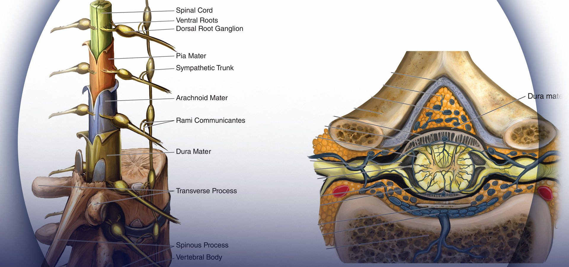
Optimizing an ultrasound image is an essential skill during ultrasound-guided nerve block. Anatomically, a peripheral nerve is always located in the vicinity of an artery between fascial layers. The echotexture of normal nerve shows a hyperechoic, hypoechoic, or honeycomb pattern (Figure 1).
")
FIGURE 1. Echotexture of peripheral nerves. (Reproduced with permission from Hadzic A: Hadzic’s Peripheral Nerve Blocks and Anatomy for Ultrasound-Guided Regional Anesthesia, 2nd ed. New York: McGraw-Hill, Inc.; 2011.)
There are several scanning steps to obtain adequate nerve imaging, including the selection of sonographic modes, adjustment of function keys, needle visualization, and interpretation of image artifacts.
NYSORA Tips
• It is often easier to identify easily recognizable structures in the vicinity of the nerve, then to look for the nerve structures upfront.
Common sonographic imaging modes used for medical diagnostics, such as, conventional imaging, compound imaging, and tissue harmonic imaging (THI) can all be utilized in imaging of peripheral nerves. Conventional imaging is generated from a single-element angle beam at a primary frequency designated by the transducer. Compound imaging is implemented by acquiring several (usually three to nine) overlapping frames from different frequencies or from different angles. THI acquires the information from harmonic frequencies generated by ultrasound beam transmission through tissue. Harmonic frequencies are multiples of the primary frequency. THI improves axial resolution and boundary detection by suppression of scattering signals from tissue interfaces, especially for obese patients.
Currently, THI has been set as the default mode by many, if not most, US manufacturers. Compound imaging with THI can provide images with better resolution, penetration, and interfaces and margin enhancement compared with conventional sonography. In Figure 2, both compound imaging and conventional imaging were employed to visualize an interscalene brachial plexus. There is clear margin definition of two hypoechoic oval-shaped nerve structures in compound imaging; the contrast resolution between anterior scalene muscle and surrounding adipose tissue is increased in comparison with conventional imaging.
")
Five function keys on an ultrasound machine are of crucial importance to achieve an optimal image during the performance of peripheral nerve imaging (Figure 3).
- Depth: The depth of the nerve is the first consideration when an ultrasound-guided nerve block is performed.
Peripheral nerve branches have a great variation of depth, which depends on patients’ habitus; the optimal depth setting can provide good focusing properties for imaging. Table 1 recommends the initial depth and frequency settings for common peripheral nerve blocks. The target nerve should be at the center of ultrasound imaging because it not only has the best resolution of the nerve but also reveals the other anatomical structures in the vicinity of the nerve. For example, ultrasound imaging during supraclavicular or infraclavicular brachial plexus block must require that the first rib and pleura are observed simultaneously to avoid lung puncture with the needle. - Frequency: The ultrasound transducer with the optimal frequency range should be selected to best visualize the target nerves. Ultrasound energy is absorbed gradually by the transmitted tissue; the higher the frequency of ultrasound, the more rapid the absorption and the less distance propagation. Therefore, a low-frequency transducer is used to scan structures at a deeper location; unfortunately, this is at the expense of reduced image resolution. In some particular cases, like lumbar plexus block, a lower-frequency transducer with a Doppler setting is useful for identifying the vasculature close to the lumbar plexus in obese patients.
- Focusing: Lateral resolution can be improved by choosing a higher frequency as well as by focusing the ultrasound beam.
In clinical practice, the focus is adjusted at the level of the target nerve; the best image quality for a given nerve is obtained by choosing an appropriate frequency transducer and the focal zone (Figure 4A). Furthermore, when possible, selecting no more than two focus zones yields better image because multiple focal zones can slow the frame rate and decrease the temporal resolution. - Gain: Screen brightness can be adjusted manually by two function buttons—gain and time-gain compensation (TGC)—on ultrasound machines that have TGC built in. Excessive or inadequate gain can cause blurring of tissue boundaries and loss of information. Optimal gain for scanning peripheral nerves is typically the gain at which the best contrast is obtained between the muscles and the adjacent connective tissue. This is because muscles are wellvascularized tissue invested with connective tissue fibers, whereas the echo texture of connective tissue is similar to that of nerves. In addition, increasing gain below the focus works well with the TGC control to visualize both the target nerve and the structures below it. Figure 4B shows the same section with both correct and incorrect gain and TGC settings. TGC sliders aligned in a curve can lead to a desirable image with appropriate gain.
5. Doppler: In regional anesthesia, Doppler ultrasound is used to detect vascular structures or the location of the spread of the local anesthetic injection. Doppler velocity scale is best set between 15 and 35 cm/s to reduce aliasing of color Doppler imaging and artifacts of color (Figure 5). Of note, power Doppler is more sensitive for detecting blood flow than color Doppler. The gate size is another common setting when color Doppler is used. It should be as small as possible to overlay the area of interest. An appropriate small gate not only can exclude distractive signals from adjacent tissues but also can improve temporal resolution by increasing the frame rate.
. (Reproduced with permission from Hadzic A: Hadzic’s Peripheral Nerve Blocks and Anatomy for Ultrasound-Guided Regional Anesthesia, 2nd ed. New York: McGraw-Hill, Inc.; 2011.)")
FIGURE 3. Optimizing an ultrasound image using five key functional adjustments and specific tips on adjusting the focus and gain. Some ultrasound models are specifically optimized for regional anesthesia application and may not incorporate user-adjustable focus or time-gain compensation (TGC). (Reproduced with permission from Hadzic A: Hadzic’s Peripheral Nerve Blocks and Anatomy for Ultrasound-Guided Regional Anesthesia, 2nd ed. New York: McGraw-Hill, Inc.; 2011.)
NYSORA Tips
• When excessive pressure is applied on the transducer during imaging, small- and medium-size vessels may collapse and not be detected with Doppler.
TABLE 1. Suggested optimal imaging depth and frequency for common peripheral nerve blocks.
| Field Depth (cm) | Frequency (MHz) | Peripheral blocks |
|---|---|---|
| <2.0 | 12–15 | Wrist, ankle block |
| 2.0–3.0 | 10–12 | Interscalene, supraclavicular, axillary brachial plexus block |
| 3.0–4.0 | 10–12 | Femoral nerve block, TAP block |
| 4.0–7.0 | 5–10 | Infraclavicular, popliteal, subgluteal sciatic nerve blocks |
| 7.0–10.0 | 5–10 | Pudendal, gluteal sciatic nerve, lumbar plexus block |
| >10.0 | 3–5 | Anterior approach to sciatic nerve, celiac ganglion block |
")
FIGURE 4. A: Focusing narrows ultrasound beam width to improve the lateral resolution and sensitivity. Shown are three examples of focusing when imaging the sciatic nerve: below the nerve, at the level of the nerve, and superficial to the nerve. B: Optimal and incorrect gain and TGC settings. (Reproduced with permission from Hadzic A: Hadzic’s Peripheral Nerve Blocks and Anatomy for Ultrasound-Guided Regional Anesthesia, 2nd ed. New York: McGraw-Hill, Inc.; 2011.)

FIGURE 5. Color Doppler aliasing occurs when the velocity scale for color Doppler is set too low.
Two needle insertion techniques with relevance to the needletransducer relationship are commonly used in ultrasoundguided nerve block: the in-plane and out-of-plane techniques (Figure 6). An in-plane technique means the needle is placed in the plane of the ultrasound beam; as a result, the needle shaft and the tip can be observed in the longitudinal view in real time as the needle is advanced toward the target nerve.

NYSORA Tips
• Catheters often cannot be visualized by ultrasound because they coil within the tissue sheaths. Visualization of the spread of injectate is the most convenient and important method to ascertain the position of the catheter tip in the desired tissue plane.
When the needle path is not seen on the image, the needle advancement should be paused; tilting, sliding or rotating the transducer can bring the ultrasound beam into alignment with the needle. In addition, a subtle, fast needle shake and or injection of a small amount of injectate may help depict the needle location. The out-of-plane technique involves needle insertion perpendicular or any other angle to the transducer to the transducer.
The needle shaft is imaged in a cross-sectional plane and often can be identified as a bright dot in the image. Visualization of the tip of the needle, however, requires higher degree of skill. The method used to visualize the tip of the needle is as follows: Once a bright dot (shaft) is seen in the image, the needle can be shaken slightly or the transducer can be tilted toward the direction of needle insertion simultaneously until the dot disappears. Shaking the needle helps differentiate the echo as emanating from the needle or from the surrounding tissue. The last capture of the hyperechoic dot is its tip. A small amount of injectate can be used to confirm the location of the needle tip. Whenever injectate is used to visualize the needle tip, attention must be paid to avoid resistance (pressure) to injection because when the needle-nerve interface is not well seen, there is a risk for the needle to be against the nerve or to inject intrafascicularly.
NYSORA Tips
• If the needle trajectory is lost visually, the operator should stop advancing the needle and then tilt the transducer to visualize the needle.
• When the spread of the local anesthetic is not seen during the injection process, the operator should stop the injection, tilt the transducer, and inject a tiny amount of local anesthetic (or air) to locate the needle tip and spread of injectate.
Continuous peripheral nerve blocks (CPNBs) have become a common practice; however, the visualization of the catheter tip can be challenging. Direct visualization of the catheter tip can be obtained when the catheter is introduced at a short distance from the needle tip (eg, 2 cm past the needle tip) (Figure 7).
However, when the catheter is inserted 3–5 cm past the needle tip, the needle, nerve, and catheter are never in the same plane of the ultrasound beam, therefore becoming challenging to image. There are two ways to confirm the catheter tip: (1) The operator can tilt or slightly slide the transducer to see a “bright dot,” which is the transverse view of the catheter. The position of the catheter tip can be detected by observing the spread of 1–2 mL injectate through the catheter, and the use of color Doppler may help visualize the spread more significantly (Figures 8A and 8B). (2) In some cases, the bright dot may not be obviously visualized or ensured; the operator has to slide the transducer within a certain distance away from the needle tip, with the distance based on the length of catheter threaded past the needle tip. Injection of 0.5 mL air can be beneficial to ascertain the position of the catheter tip with a sharp echoic contrast on the ultrasound image (Figures 9A and 9B). The obvious drawback is that injection of air may degrade the image for other purposes.

FIGURE 7. The catheter tip can be directly seen just beneath femoral nerve.

FIGURE 8. A: The position of catheter tip can be estimated by observing the spread of injectate. B: Doppler can be used to confirm the location of the spread.

FIGURE 9. A: The location of the catheter tip cannot be visualized before a small amount of air is injected. B: The discernablebrightness indicates the location of the catheter tip when 0.3–0.5 mL air is injected.
Ultrasound artifacts occur commonly and, in fact, are an intrinsic part of ultrasound imaging. By definition, an ultrasound artifact is any image aberration that does not represent the correct anatomic structures. Most artifacts are undesirable, and operators must learn how to recognize them during nerve block. The five artifacts most commonly seen in regional anesthesia practice (Figure 10) are the following:
")
FIGURE 10. Five common ultrasound artifacts during ultrasound-guided peripheral nerve block. (Reproduced with permission from Hadzic A: Hadzic’s Peripheral Nerve Blocks and Anatomy for Ultrasound-Guided Regional Anesthesia, 2nd ed. New York: McGraw-Hill, Inc.; 2011.)
1. Shadowing is a significant attenuation of ultrasound signal deep to tissues and structures that absorb or reflect most of the ultrasound waves, as bones, calcifications or air. This is manifested by a weak or absent echo area which appears as a shadow on the imaging behind a bright, hyperechoic interface. Acoustic shadowing has a favorable diagnostic value for detection of calcified lesions, such as gallstones, scar tissue, and the like. However, the shadowing may interfere with nerve visualization in regional anesthesia. Changing the scanning plane to find the best acoustic window is the best strategy to avoid shadowing when necessary.
2. Enhancement manifests as overly intense echogenicity behind an object (a fluid-filled structure, such as a vessel or cyst) that is less attenuating than the surrounding soft tissues. Enhancement occurs when the echo signals are overamplified in brightness disproportional to the echo strength at the same depth. Scanning from different angles or from different planes may help to decrease shadowing/enhancement artifacts and to visualize the target nerve; using automatic TGC may make enhancement artifact less apparent as well.
3. Reverberation displays in the form of parallel, equally spaced bright linear echoes behind the reflectors in the near field of the image. The multiple echoes occur when the ultrasound beam bounces repeatedly between the interfaces of the transducer and a strong reflector, especially when these two interfaces are parallel to each other. It may be attenuated or eliminated when the scanning direction is changed slightly or the ultrasound frequency is decreased.
4. Mirror image artifact results from an object located on one side of a highly reflective linear boundary that acts like an acoustic “mirror,” appearing on the other side as well. The transducer receives both direct echoes from the object and indirect echoes from the mirror (Figure 11). Both virtual and artifactual images have an equal distance to the mirror from opposite directions. The duplicated artifactual image is always less bright and deeper than the real image because indirect echoes transmit a longer distance and attenuate more wave energy. Changing the scanning direction may decrease the artifact. Velocity error is the displacement of the interface, which is caused by the difference of actual velocity of ultrasound in human soft tissue, compared with the calibrated speed, which is assumed to be a constant velocity of 1540 m/s set by the ultrasound system. Consequently, a reflector is displaced toward the transducer by a significant error in distance calculations. The inherent artifact in the process of scanning cannot be completely eliminated in all cases by manipulating ultrasound devices or changing the settings. However, recognizing and understanding ultrasound artifacts help the operator avoid misinterpretation of images.
 and indirect echoes from the “mirror” (2).")
FIGURE 11. Mirror image artifact: Transducer receives both direct echoes from the object (1) and indirect echoes from the “mirror” (2).
PREPARING TO SCAN
An acronym, SCANNING, can be used by operators to prepare for scanning:
S: Supplies
C: Comfortable positioning
A: Ambiance
N: Name and procedure
N: Nominate transducer
I: Infection control
N: Note lateral/medial/superior/inferior orientation on screen
G: Gain depth
1. Gather supplies: All equipment necessary for ultrasound scanning should be prepared. Equipment may differ slightly depending on the area to be scanned; however, some necessary equipment includes the following:
a. Ultrasound machine
b. Transducer covers
c. Nerve block kit, nerve stimulator
d. Sterile work trolley
e. Local anesthetic drawn up and labeled
f. Whenever possible, connect the ultrasound machine to the power outlet to prevent the machine from powering down during a procedure. Although many point-of-care ultrasound machines are equipped with batteries, these run out of power during the most importunate part of the procedure.
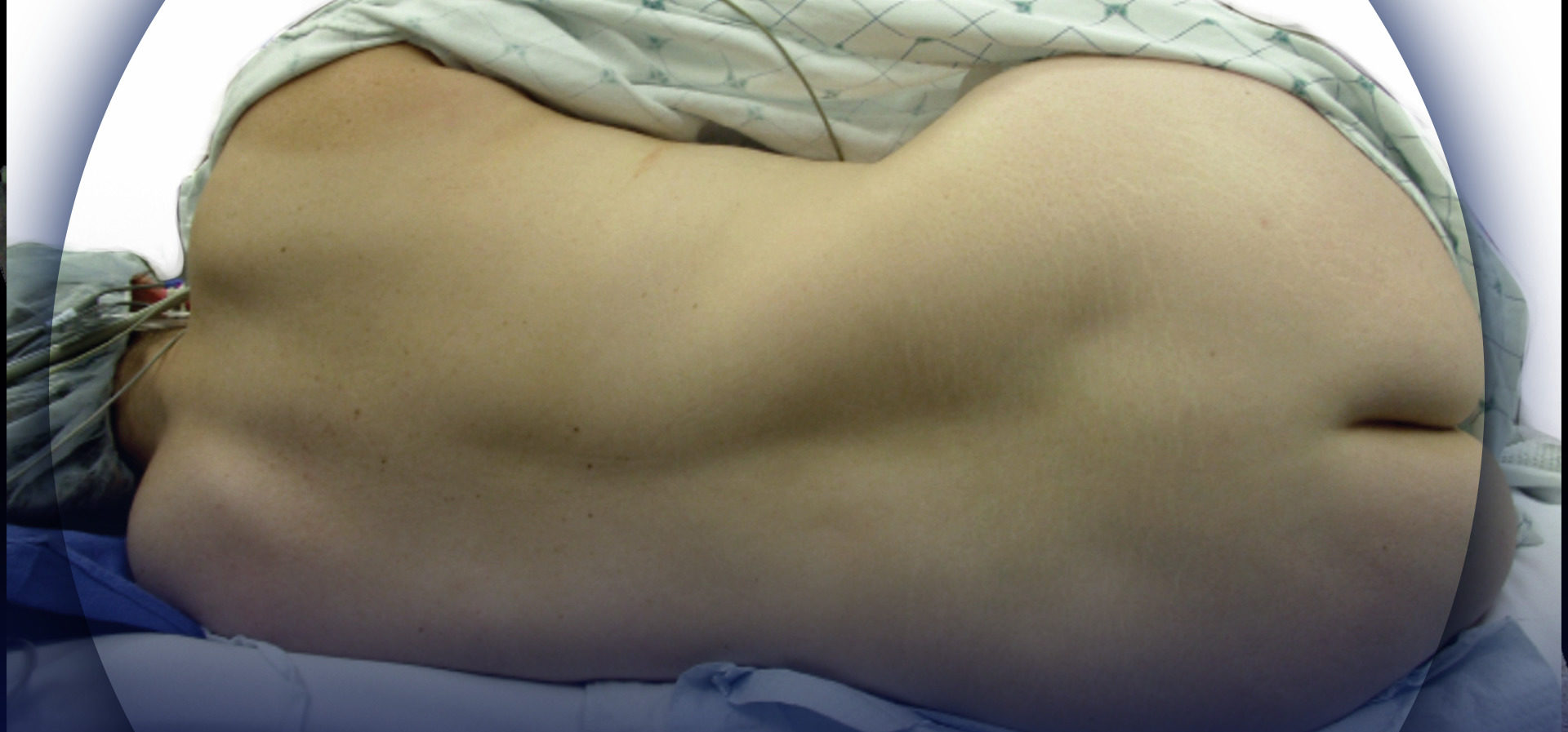
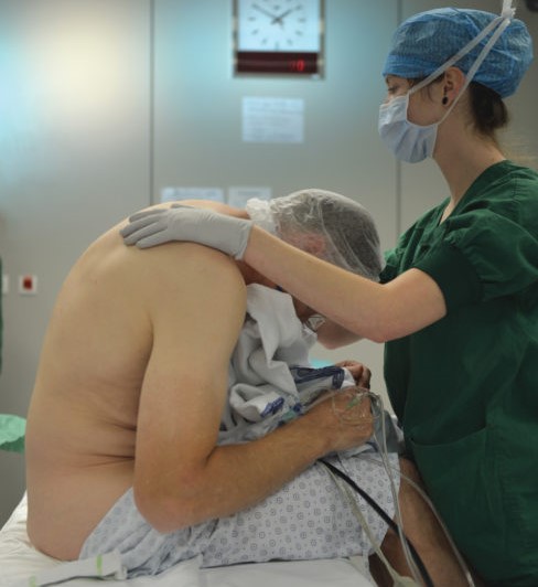
2. Comfortable patient position: The patient should be positioned in such a way that the patient, the anesthesiologist, the ultrasound machine, and the sterile block tray are all arranged ergonomically to allow for timeefficient performance of the procedure.
a. The ultrasound machine should be set up on the opposite side of the patient from the operator with the screen at the operator’s eye level.
b. The block tray should be positioned close enough to the operator can easily reach for needle, gel, and other supplies without interference with the scanning procedure.
3. Ambiance set room settings: Adjust the lights in the room to view the ultrasound machine and procedural site adequately.
a. Dim lighting optimizes visualization of the image on the screen; more lighting may be needed for the procedural site.
b. Adjust the room light settings to allow for proper lighting to both areas, as well as for safe monitoring of the patient.
4. Name of patient, procedure, and site of procedure: Before performing a scan take a “time-out” to ensure patient information is correct, the operation being done is confirmed, and the side in which the procedure is being done is validated. The New York School of Regional Anesthesia (NYSORA) team uses the acronym ECT for the time-out procedure: E for equipment for patient monitoring and needle-nerve monitoring; C for the patient’s consent for the procedure; and T for the time for the time-out to identify the patient and ensure correct laterality. Checking that patient information is entered into the ultrasound machine and matches the information on the patient’s wristband not only confirms identity but also allows for images to be saved during the scanning process for documentation.
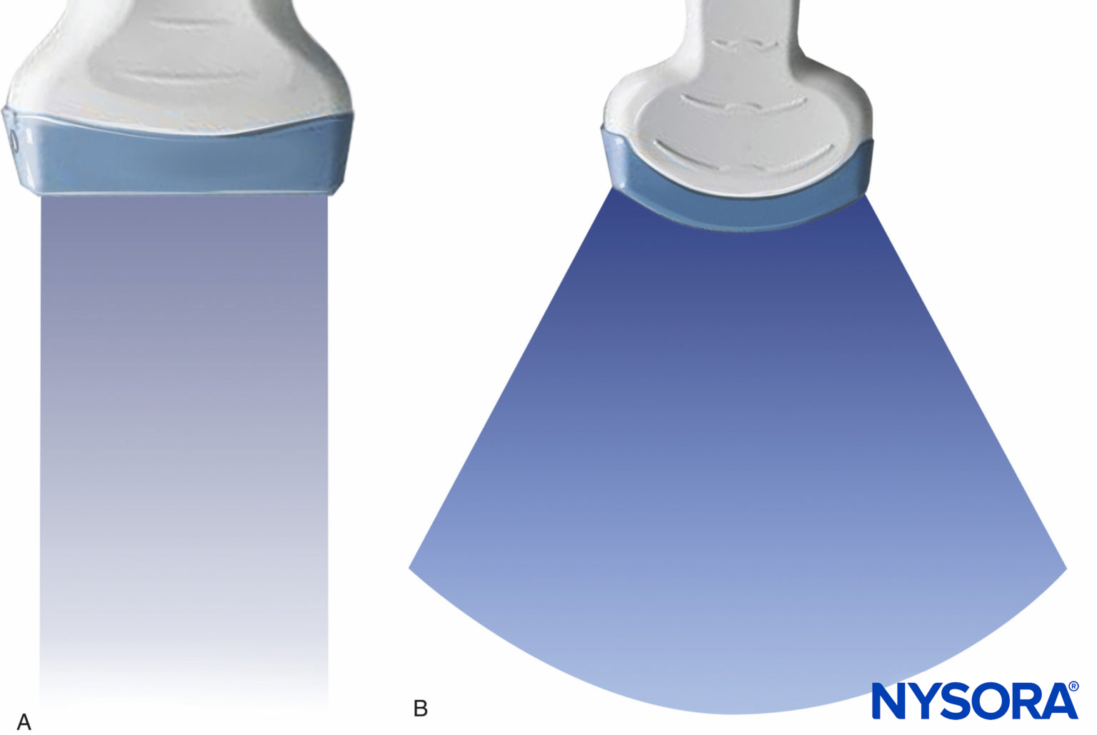
5. Select transducer: Select the transducer that best fits the scheduled procedure. A linear transducer is best for scanning superficial anatomic structures; a curved (phased-array) transducer displays a sector image and is typically better for deeper-positioned structures. A hockey stick ultrasound transducer is an ideal choice for vascular access or a superficial block with limited space, such as an ankle block.
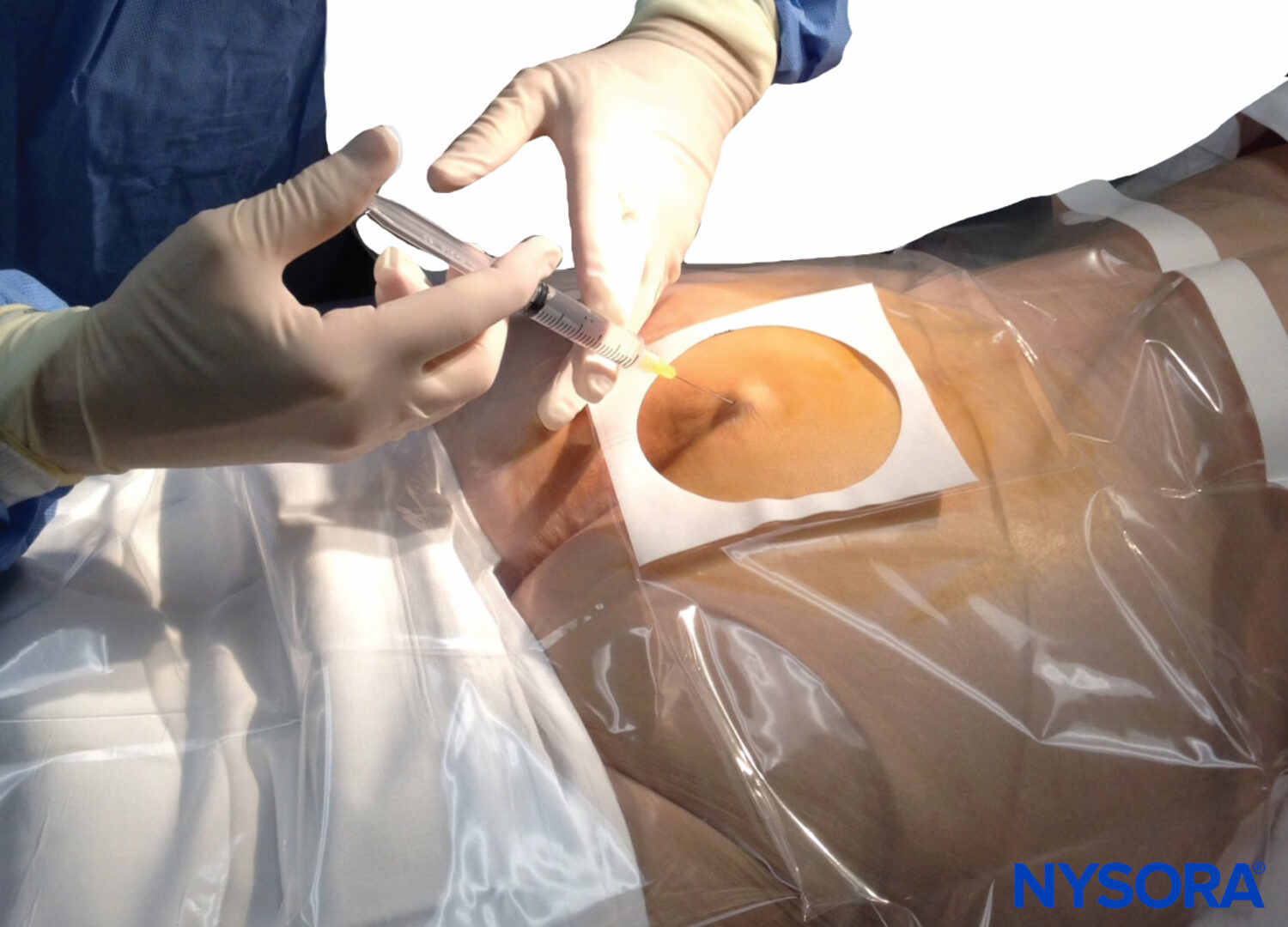
6. Disinfection: Disinfect the patient’s skin using a disinfectant solution to reduce the risk of contamination and infection.
7. Orient transducer and apply gel: The operator should orient the transducer to match the medial-lateral orientation of the patient. This is conventionally not done by radiologists/sonographers, but it is useful for intervention-oriented regional anesthesia procedures.
a. Touch one edge of the transducer to orient the side of the transducer so the medial-lateral orientation on the patient corresponds to that on the screen.
b. A sufficient amount of gel is applied to either the transducer or the patient’s skin to allow for transmission of the ultrasound. A copious amount of disinfectant solution can be used instead of gel in many instances.
c. Insufficient quality of gel will decrease reflectionabsorption rates and may result in unclear/blurry images on the ultrasound image being displayed.
8. Place the transducer on the patient’s skin and adjust the ultrasound machine settings:
a. The gain should be adjusted with the general gain setting or by using TGC.
b. The depth is adjusted to optimize imaging of the structures of interest.
c. Where available, focus point level.
d. Scanning mode can be switched to assist in the recognition of the structures as necessary. Power Doppler can help depict blood vessels; color mode can distinguish between arteries and veins.
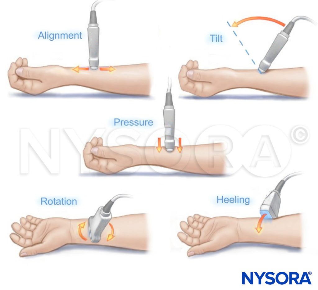
TRANSDUCER MANEUVERS