 Nerve Blocks App
 Pain Medicine Assistant App
 POCUS App
 IV Access App
 MSK Knee App
 VetRA App
 Nerve Block Manual
 Regional Anesthesia Updates
 Anesthesiology Manual
 Anesthesiology Review
 Anesthesia Updates 2025
 Anesthesia Updates 2026
 Pediatric Anesthesia Updates
 Airway Management Updates
 US Interventional Pain Manual
 Pain Medicine Updates
 Mastering Difficult IV Access
 PACU Nursing Manual
 RA Veterinary Manual
 About
About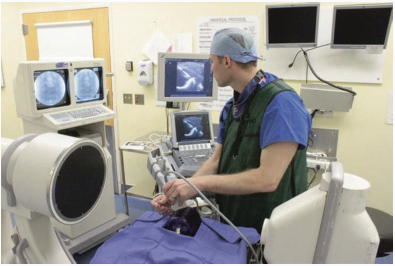
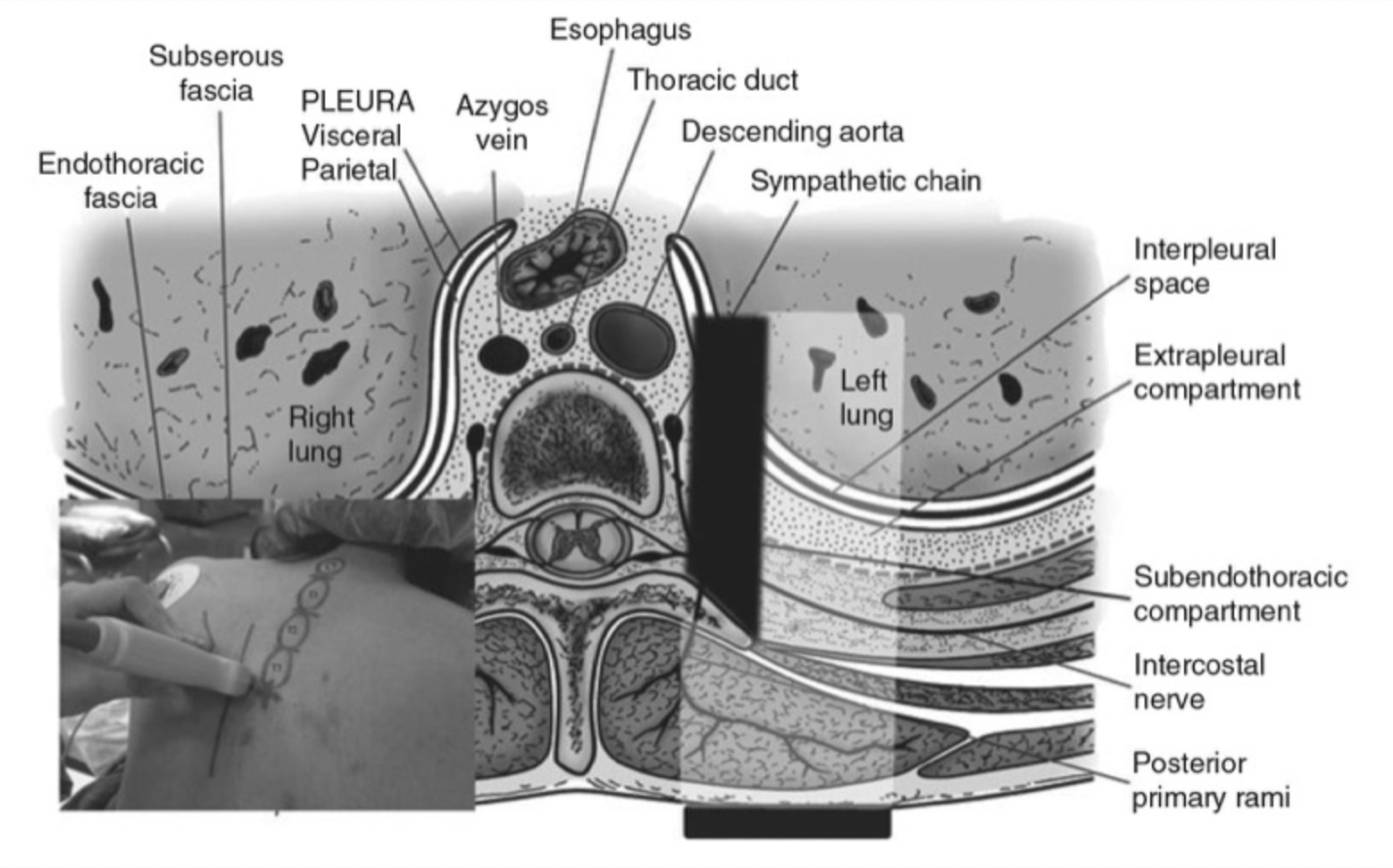
There are many advantages to the use of ultrasound in interventional pain medicine procedures. Ultrasound technology is currently growing exponentially due to its many advantages of improved and real-time high-resolution ultrasound imaging that results in successful pain management interventions. In addition, use of ultrasound for interventional pain management procedures avoids the many risks associated with radiation exposure to both the patient and practitioner. With appropriate training and experience, reliable and compulsive tracking of an introduced needle shaft and tip, both critical for effective and safe pain medicine interventions, may be mastered. Failure to visualize the needle, especially the needle tip, during needle advancement is one of the most common errors in ultrasound-guided interventional procedures (UGIP). Manipulation of the needle positioning during a pain management intervention, injection of local anesthetics/steroids or other medications, radiofrequency or cryoablation procedures, and other interventions without adequate needle tip visualization can often result in unintentional vascular, neural, and visceral injury. As an example, the rate of unintentional vascular puncture injuries during peripheral nerve block placement was reduced from 40% in the conventional anatomical landmark techniques to 10% with introduction of real-time visualization of the advancing regional block needle under ultrasound. Trainees can often make repeated errors and exhibit potentially compromising technical and safety behaviors during ultrasound-guided interventional nerve block placement procedures which can be potentially remediated by techniques that can improve needle visualization. A practitioner cannot assume that an interventional/procedural needle will always be clearly identified based on the variable properties and sizes of the several metallic needles. The variety of needle types used will often produce a distinct signal or “echo” under the ultrasound image. Effective visualization of the procedural needle, once introduced under the skin, is challenging for several reasons: variability in echogenicity of needles, varying ultrasound machine image processing technologies by the many ultrasound manufacturers, and transducer probe properties variability. These reasons along with other factors may be manipulated and modified to help improve needle visibility and will be discussed in this course.
1. TRAINING AND PHANTOM SIMULATION
Training with Adequate Mentorship
An adequate knowledge of human anatomy and ability to produce “typical” cross-sectional anatomical images during sonography are usually not sufficient for adequate needle visualization under all circumstances. The ability to observe, in real-time, needle placement and advancement along with several other procedural manipulations under ultrasound guidance can be a challenging task to both the experienced practitioner and novice as it requires a new set of skills. Sites et al. has shown that simultaneous needle manipulation along with device operation requires dedicated training despite other tendencies to define simple training strategies for ultrasound use by non-radiologists. The American Society of Regional Anesthesia and Pain Medicine and the European Society of Regional Anaesthesia and Pain Therapy Joint Committee suggested that visualization of needle passage along with local anesthetic injection is one of the four important categories of skill required for proficiency in UGIP including understanding device operations, image optimization, and image interpretation (Fig. 1).
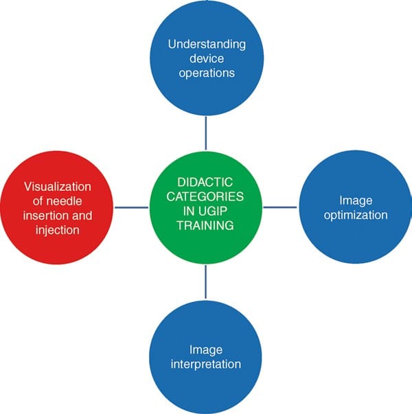
Fig. 1 Major didactic categories in UGIP training include visualization of needle insertion and injection of local anesthetic solution, understanding device operations, in addition to image optimization and interpretation. UGIP ultrasound-guided interventional procedures.
In order to become more proficient at these four technical skills, it requires that the practitioner undergo adequate training that includes a continuing medical education regimen under mentorship supervision and instruction. In order to continue to develop the skill set necessary to become more proficient with UGIP, one should also perform ultrasound scanning on self and colleagues and practice on simulators and phantoms prior to performing UGIP on patients.
Phantoms
Two common errors during UGIP training have been identified, and they are
1. failure to visualize the procedural needle during advancement toward its target and
2. ultrasound probe movement without proper needle visualization.
An ultrasound phantom is a simulation tool that mimics several properties of human tissue including tactile texture and compressibility of human skin, in addition to the typical needle appearance and feel as it is passed under ultrasound. UGIP phantom simulation may also address some important patient safety concerns by improving needle manipulation skills and further develop abilities with needle tip visualization that will alleviate many of the stressors associated with practicing UGIP on patients. Practicing ultrasound-guided needle tip visualization on a phantom simulator will begin to foster development of the necessary skill set for UGIP in a less stressful and low-risk setting.
Various modalities have been described to accomplish a “tissue-like” appearance of practice phantoms for ultra-sound. Phantoms are typically identified by their “fidelity” that describes how closely the phantom can replicate the accurate texture of anatomical tissue. For example, a high-fidelity phantom would be a cadaver specimen, and a low-fidelity phantom would be represented by a water bath. Low-fidelity phantoms have been made from many different materials including water balloons or water baths (Fig. 2), tofu (Fig. 3), gelatin or agar, or readily available materials, such as surgical gel pads (Fig. 4). There have been other simulators described including sponges, cheese, chicken, turkey, porcine phantoms, and other objects. These strategies reflect a growing interest in continued development of newer high-fidelity phantom technologies.
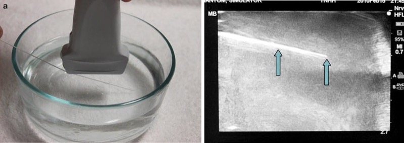
Fig. 2 Needle appearance in water bath phantom (a, b). This is a water bath phantom (a); the needle (arrows) is easily visualized (b).
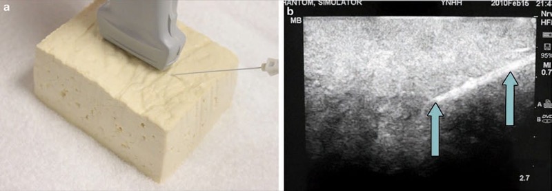
Fig. 3 Needle appearance in tofu phantom (a, b). Tofu is an inexpensive ultrasound phantomCaption(a) where the needle (arrows) is easily visualized (b).
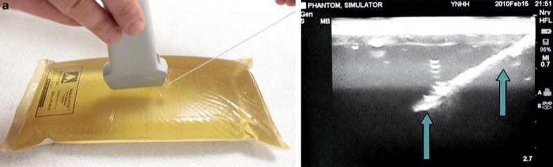
Fig. 4 Needle appearance in surgical gel pad (a, b). This is a surgical gel pad phantom (a). Here the needle (arrows) is easily visualized (b).
The low-fidelity phantoms have limited durability, and limitations in sonographic fidelity may also be present. Most recently, phantom simulation technology has improved, and phantoms can be made of polymer plastics, polyurethane, and other vinyl materials. As another example, the Blue Phantom (Fig. 5) (Redmond, WA) and ATS laboratories phantoms (Bridgeport, CT) (Fig. 6) will appear “tissue-like” under ultrasound imaging and can also include vessels, while some others can include phantom nerves or spine (Fig. 7).
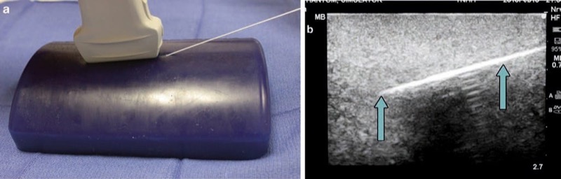
Fig. 5 Needle appearance in Blue Phantom (a, b). Blue Phantom is an ultrasound phantom that includes structures, simulating nerves, and vessels (a). Here the needle (arrows) is easily visualized (b).
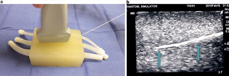
Fig. 6 Needle appearance in ATS laboratories phantoms (a, b). The ATS phantom incorporates plastic tubes that simulate vessels (a). The needle (arrows) is easily visualized (b).
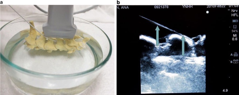
Fig. 7 Needle appearance in cervical spine water bath phantom simulator (a, b). A water bath cervical spine and lumbar spine phantom simulate bony structures of the spine. Panel (a) shows a cervical spine model in a water bath. Panel (b) shows the cervical spine under ultrasound with needle (arrows) easily visualized.
2. HIGH-FIDELITY SIMULATION
The ultrasound-guided regional anesthesia simulation phantom (U-GRASP) interactive tool (IT), a newer type of ultra-sound simulator, has been developed by authors for the trainees mastering their needle visualization technique (Fig. 8). The U-GRASP IT includes a correct phantom that can mimic extremity movement when the ultrasound-guided target is reached and successful neurostimulation is achieved. In addition, the phantom provides feedback in the form of an activating buzzer and an illuminating light-emitting diode when a successful block has been performed. The future of simulator phantoms will continue to expand and possibly include error and skill assessment in targeted needle advancement, and the data may also be used to score and track UGIP training with an emphasis on improving UGIP outcomes. Recently, there has been development of virtual and 3D/4D UGIP phantoms that are similar to what is being used in surgical training.
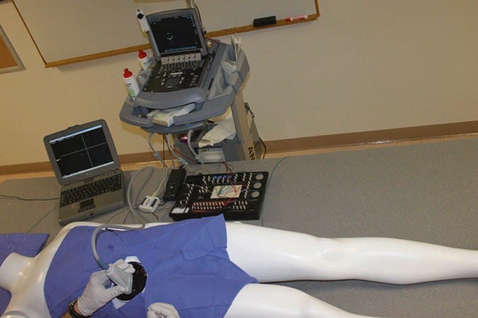
Fig. 8 Ultrasound-guided regional anesthesia simulation phantom (U-GRASP) interactive tool (IT). This is a high-fidelity ultrasound simulator that allows documentation of trainee performance in the needle positioning during simulated procedures. In addition, it provides the trainee with the immediate feedback through a light and a sound indicator which activates as the targeted anatomical structure is approached with the needle tip.
Some of the ultrasound machines for UGIP provide multimedia tools to facilitate learning of the UGIP. The devices allow the use of the bank of preset images and video of typical procedures and anatomical cross sections which can be utilized during the procedure of choice to provide a real-time on-hand high-quality reference and image interpretation support (Fig. 9).
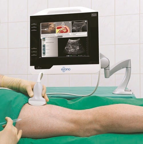
Fig. 9 Real-time and image interpretation support system (eZONO). The eZONO device allows the operator to use a bank of stored preset images and video and anatomical cross-sections which can be used during the procedure of choice to provide a real-time on-hand high-quality reference and image interpretation support. Used with permission from eZONO.
3. COMBINED ULTRASOUND AND FLUOROSCOPIC PHANTOM SIMULATORS
Many pain practitioners are unfamiliar with UGIP and have no experience or little understanding of ultrasound needle visualization and needle manipulations under ultrasound. These individuals most likely learned and then practiced acquisition of needle tracking skills that are required for the many different types of injections (e.g., cervical and lumbar spine) by simultaneous simulation of X-ray-based techniques and ultrasound simulator. This combination was found to be helpful in the transition from computer tomography-assisted injections for low back pain to the now developing area of UGIP. However, high-fidelity anatomical and animal lab ultrasound phantoms are currently found most often at university centers or at special conferences and seminars and not widely accessible. A prototype of a combined ultrasound and fluoroscopic phantom for cervical transforaminal injections has been developed by authors. It is made from a commercially available cervical spine anatomical model submersed in a polyvinyl medium sonographically simulating human tissue. In addition, this phantom contains anatomical examination and will uptake fluoroscopic dye if mistakenly injected (Fig. 10). Easy to reproduce, this high-fidelity simulation system may improve trainee proficiency in needle visualization during combined ultrasound-guided and fluoroscopic UGIP.
Fig. 10 Combined ultrasound and fluoroscopic phantom for cervical transforaminal injections. This phantom contains anatomically correct fluid-filled vertebral arteries that exhibit pulsed flow under ultrasound Doppler examination and will uptake fluoroscopic dye if mistakenly injected through procedural needle. The picture demonstrates the phantom used by a resident physician.
There is a growing body of evidence along with proven benefit for both technical and “hands-on” skill improvement when simulation of needle localization during UGIP is introduced in surgery, emergency medicine, interventional radiology, and anesthesiology. To establish the utility and cost-effectiveness of technologically advanced simulators, future studies will need to compare high-fidelity vs. lower-fidelity models. In addition, there are many other medical specialties that have shown the advantage of simulation on improving manual dexterity which may translate into improved procedural outcomes. The field of pain medicine is rapidly advancing and will surely benefit from incorporating simulation into pain medicine education and training that may also provide a high-yield strategy for overcoming some of the challenges of needle visualization during UGIP.
4. PROCEDURAL NEEDLE: RELATED VISIBILITY FACTORS
Basic Sonography and Needle Image Interpretation
One of the important components of an ultrasound machine is the ultrasound transducer (referred to as a probe or scan head). This ultrasound probe transmits sound waves, which culminate in an acoustic beam that is generated by an alternating electrical field applied to small piezoelectric crystals located under the ultrasound transducer surface. Typical sound wave frequencies used in UGIP are “ultra” high, within the range of 3–15 MHz, thus the terminology of ultrasound. The ultrasound beam is directed away from the transducer footprint and can penetrate through the tissue to varying degrees depending upon tissue composition. An acoustic beam can penetrate through muscle, tendon, and other soft tissues to varying degrees depending upon the density of the particular tissue, yet sound waves cannot pass through extremely dense tissue such as bone. The sound waves generated to and through the tissue will then be reflected back (to varying degrees) to the ultrasound transducer. Therefore, an ultrasound image results when the transmitted from the ultrasound probe acoustic beam is reflected back to the ultrasound transducer. The ultrasound probe serves not only as the generator of the ultrasound beam but also serves as the receiver of the “echo,” which relays data back to the console and display screen to formulate an image. When a UGIP intervention is performed, the inserted procedure needle being used reflects sound waves back to the ultrasound probe that then deforms the piezoelectric crystals of the transducer to produce an electrical pulse or “echo.” The time taken for an ultrasound acoustic beam to return back to the ultrasound probe is proportional to the depth at which the beam is reflected. This relationship is termed the “pulse-echo principle” and serves as the basis for real-time visualization of UGIP. Understanding the basic physics principles of sonography will permit the practitioner to continue to improve adequate needle visualization during UGIP and remains crucial for the performance of safe and effective UGIP interventions.
5. ACOUSTIC IMPEDANCE AS THE BASIS FOR PROCEDURE NEEDLE VISUALIZATION
Another essential aspect of needle visualization in UGIP is to understand the factors that can change or alter the visibility of ultrasound images such as acoustic impedance. Acoustic impedance of body tissues is dependent on the density of the tissue and the speed at which the ultrasound beam travels through that particular medium. Depending upon the particular body tissue that the ultrasound beam may be traveling through, the speed of sound changes and can range from 1500 to 1600 m/s. These small variations in ultrasound beam speed are responsible for variations in signal intensity or brightness. For instance, a part of the procedural needle that has been placed in a fluid-filled vessel will produce a bright hyperechoic signal because there is a large difference between acoustic impedance of each of the structures (needle and fluid). If there are marked differences in acoustic impedance between two different tissue types, for example, between soft body tissues and a metallic needle or bone, then the brighter or more hyperechoic the sonographic signal of the needle becomes. This acoustic impedance difference between a needle and soft tissue provides an additional basis for improved needle visualization.
6. SIZE (GAUGE) OF THE PROCEDURE NEEDLE AND ITS ECHOGENICITY
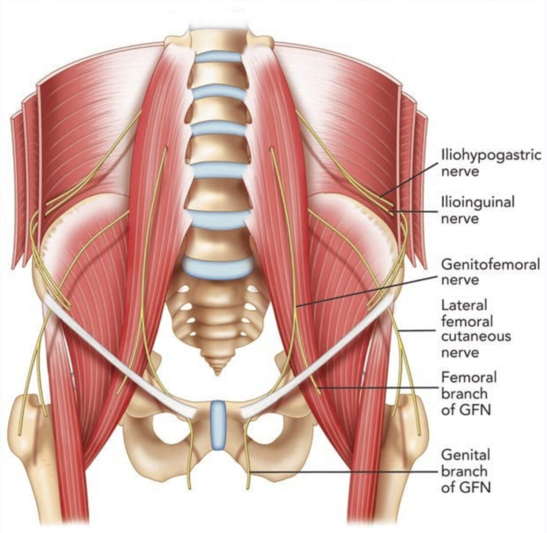
A larger caliber procedure needle is typically more easily visualized under ultrasound than a smaller size diameter needle for two important reasons. First, a large gauge (G) needle has a greater surface area that produces more significant change in acoustic impedance than a smaller G needle, and this can translate into a brighter image on the ultrasound screen. Second, the greater surface area of a larger G procedure needle can intercept the ultrasound beam, and subsequently, there is a higher probability that the ultrasound beam will be reflected back to the transducer, thus producing a brighter signal than smaller G needles (Fig. 11). As a result, larger gauge needles appropriate for pain management procedures have been recommended for improved needle visibility during UGIP. However, it must be remembered that a larger G procedure needle may be associated with more patient discomfort during needle passage through tissue. Although during a trial performed by Campos et al. to treat chronic inguinal pain, a 14 G needle and cryoablation probe were used and advanced toward the genitofemoral nerve that permitted improved needle visibility under ultrasound, patient discomfort was reduced with local anesthetic skin infiltration prior to needle passage. Appropriate selection of procedure needle G and needle length (discussed later in the chapter) should be chosen based upon the UGIP task, and it is important to note that a larger G needle does not necessarily translate into compromised patient safety. As an example, the safety of 21 and 18 G needles were found to be the same in an ultrasound-guided spleen biopsy study.
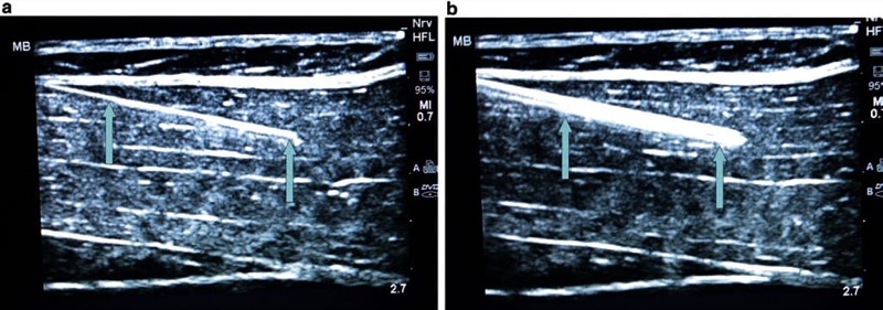
Fig. 11 Gauge (G) of the needle and its visibility (a, b). The larger the needle, the greater the ultrasound beam reflection which then improves needle visualization. Panel (a) shows 21 G needle (arrows), while an 18 G needle (arrows) is shown in panel (b). Even a small increase in needle size makes it more visible. Porcine phantom.
7. THE SKIN INSERTION SITE SELECTED AND ANGLE OF PROCEDURE NEEDLE PASSAGE
The angle and insertion site selected of a procedure needle for initial skin penetration/ insertion plays a critical role in optimizing needle visualization on an ultrasound screen. Poor choice of needle insertion site and needle angle with respect to the ultrasound probe footprint may prevent optimal, clear, and accurate needle visualization on the ultrasound screen. This aspect of behavioral training was one of the five quality-compromising patterns identified by Sites et al. during UGIP trainee behavior. If the angle of the procedure needle insertion is too steep or acute in relation to the ultrasound probe footprint surface, then a smaller or shorter portion of the ultrasound beam will be reflected back from the needle to the transducer resulting in decreased needle visibility (Fig. 12). A simple approach suggested to overcome this obstacle is to introduce the procedure needle at as much of a perpendicular angle of insertion to the ultrasound probe footprint surface/ ultrasound beam direction as possible. To obtain the most optimal sonographic image of a procedure needle, the ultrasound beam should approach the needle and be reflected back to the ultrasound probe at a perpendicular (90°) angle. When the ultrasound probe acoustic beam and procedure needle are at a 90° angle to one another, the transducer maximizes the reception of the reflected ultrasound beam from the needle. An alternative way to position the procedure needle and ultrasound probe as close to 90° to one another as possible is to press or tilt the opposite end of the ultrasound transducer using the “heel-in” maneuver (Fig. 13).
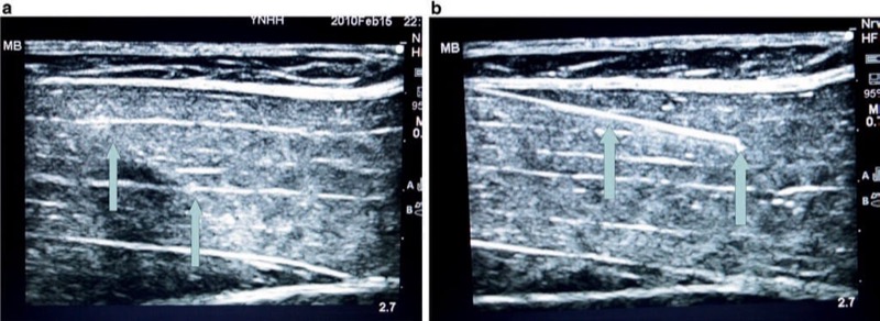
Fig. 12 The angle of the needle insertion and its visibility (a, b). The steeper the angle of needle insertion, the less the ultrasound beam reflection which then worsens the needle visualization. Panel (a) shows a steeper angle of insertion, while panel (b) demonstrates abetter visibility of the same needle, inserted under a lesser angle. Porcine phantom.
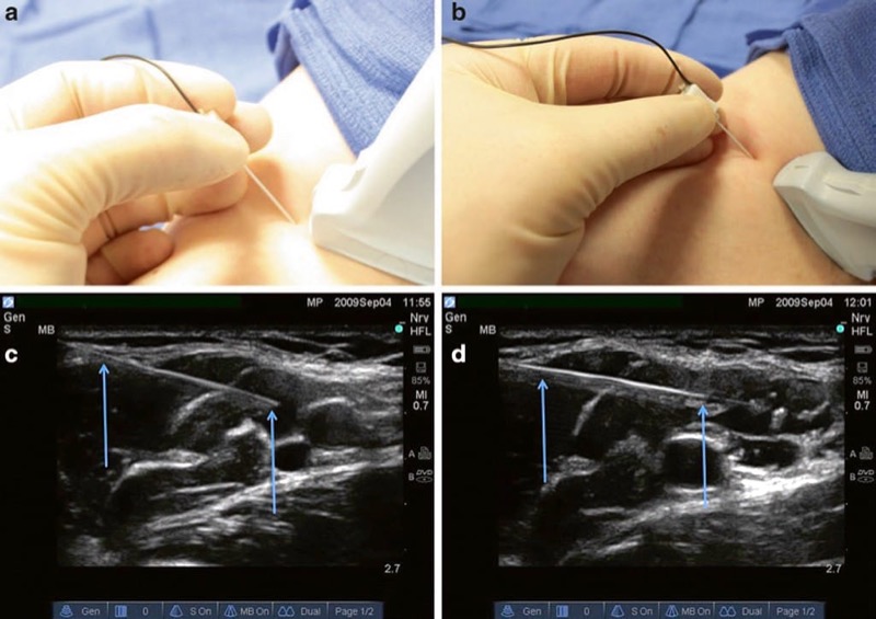
Fig. 13 Probe heel in to change the angle (a, b). The heel-in maneuver increases the angle of incidence from the probe to the needle improving reflection of the needle and improved visualization. Panel (a) demonstrates an in-plane linear probe approach. Panel (b) demonstrates an in-plane heel-in maneuver. Panel (c) demonstrates the needle (arrows) appearance with the in-plane linear probe approach. Panel (d) demonstrates the needle appearance (arrows) with the in-plane heel in maneuver.
Many regional anesthesia and UGIP procedures are performed with a linear array ultrasound probe. However, the linear array probe may produce additional patient discomfort during the tilting or heel-in maneuver used to obtain optimal procedure needle to ultrasound probe orientation. This increased sensitivity to heel-in manipulations may be especially true for certain chronic pain patients, and a potential solution to these patients’ discomfort concern is the use of a curvilinear ultrasound probe. The curvilinear probe will permit a relatively painless heel-in maneuver for almost all patients while obtaining an excellent procedure needle and ultrasound probe orientation and maximizing both tissue and procedure needle visualization (Fig. 14). However, it must be remembered that the curvilinear ultrasound probe (more ideal for deeper structures) does not provide an optimal scanning image for more superficial targets as does a linear array ultrasound transducer.
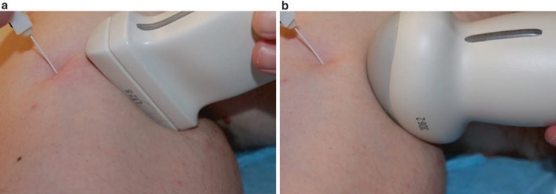
Fig. 14 Curved vs. linear probe (a, b). The heel-in maneuver is ergonomically improved with a curved ultrasound probe and has the added advantage of causing less patient discomfort. Panel (a) shows the heel-in maneuver with a linear probe. Panel (b) shows the heel-in maneuver with a curved probe.
The most optimal angle for a procedure needle to the skin surface interface is the performance of a needle insertion angle range between 30° and 45°. In various clinical situations, it may not be feasible to gain this optimal angle interface for needle insertion, so echogenic needles have been designed to overcome some of these situations (not being able to obtain more adequate angles for needle insertion). These echogenic needles can be visualized at small or steep angles of insertion to the skin in a range as low as 15–30° due to the special echogenic properties of the procedural needles.
8. ECHOGENIC PROCEDURE NEEDLES
When imaged properly, almost any procedure needle will generate an ultrasound image or return an echo under ultrasound scanning. However, needles have been designed and engineered with special properties to be used in conjunction with ultrasound that will enhance and optimize their ultrasound image quality and have been termed echogenic procedure needles. Many recent advances have provided additional properties in needle technology that will improve needle echogenicity. Small angled indentations or notches have been created in the needle shaft resulting in an irregular surface of the procedure needle that will increase the scatter of ultrasound waves. Theoretically, the irregular or notched surface of the procedure needle will provide a brighter signal and clearer ultrasound image at variable angles of needle insertion to the skin (Fig. 15). The greater number of indentations or notches created in the shaft of a procedure needle will possibly translate into improved needle visualization on the ultrasound image screen. However, as the number of indentations increases, there is a simultaneous increase in the degree of roughness of the procedure needle shaft, which may be associated with greater friction at the needle-tissue interface. The friction at the needle-tissue interface can be disruptive to the process of smooth needle movements that are necessary during a nerve block procedure and may prove to be disadvantageous and/or create additional patient discomfort.
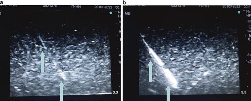
Fig. 15 Indentation improves the reflection of ultrasound (a, b). This echogenic needle has an indentation on the needle shaft that improves ultrasound beam reflection at more variable angles of insertion. Panel (a) shows a generic non echogenic needle (arrows) at an acute angle of incidence. Panel (b) shows a grooved echogenic needle (arrows) at an acute angle of incidence with improved visibility (Pajunk, USA). Blue Phantom.
The polymer-encased procedure needle is another technological advancement that improves needle echogenicity. A special polymeric needle coating, treated with a bubbling agent, creates microbubbles on the needle shaft surface during needle insertion and passage. Therefore, as the procedure needle is advanced into and through tissues, an increase in acoustic impedance is created between the tissue-needle interface, and this measure may improve needle echogenicity and ultrasound image quality (Fig. 16). In addition, when polymeric-coated needles are used during nerve stimulation and targeted nerve localization procedures, the applied polymer coat to the procedure needle shaft serves as an insulator for electrical stimulation and minimizes stimulation to tissues around the shaft of the procedure needle. The combination of the above described technological advances in procedure needle design (indentations and polymeric coating) has created a basis for development of the modern echogenic needles currently available on the market (Fig. 17). There are other engineering innovations currently under development toward improving upon procedure needle visibility for UGIP. One of these newer approaches consists of installation of a low-frequency generator at the end of the procedure needle, opposite to the procedure needle tip. This generator creates large amplitude vibrations along the needle shaft making the procedure needle more visible under ultrasound imaging. The effectiveness of this and some other promising needle design developments are currently under investigation.
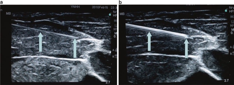
Fig. 16 Polymer-coated vs. non echogenic needle (a, b). A polymer-coated echogenic needle compared to a non echogenic needle. Panel (a) shows a 21 G non echogenic needle (arrows). Panel (b) shows a 21 G polymer-coated echogenic needle (arrows). Porcine phantom.
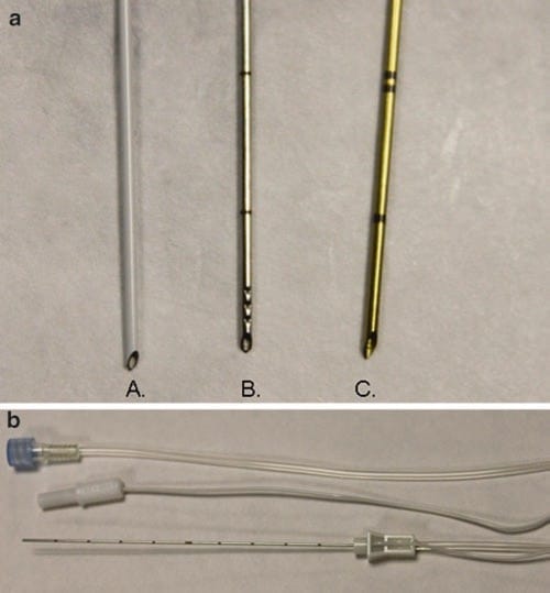
Fig. 17 Needle with indentations, covered with polymer (a, b). These are samples of neurostimulation needles with combined polymeric coating and indentations in the shaft which further improve needle echogenicity and subsequent visualization. Panel (a) A Braun, B Havels, C Pajunk needles. Panel (b), a sample of the echogenic needle with neurostimulation properties (B Braun).
A study by Phelan et al. comparing echogenic needles to standard non echogenic needles did not provide any measurable objective performance improvement for UGIP during the short-axis approach for interventional procedures. One potential disadvantage of a bright echogenic needle is the potential for an increase in unwanted shadowing from the procedure needle on the ultrasound image as well as some other artifacts. To reduce artifact created from the procedure needle shaft and to further improve upon needle tip visualization during UGIP, new technologies are focusing on developments to improve needle tip visibility rather than the entire needle shaft.
9. PROCEDURE NEEDLE TIP
Precise visualization of the UGIP needle tip is of primary importance and critical in order to minimize or avoid unintentional vascular injury or injections and other complications related to nerve and tissue damage created by procedure needles. Sites et al. have recently showed that the most common error of trainees during UGIP occurred, while residents were advancing the needle and not maintaining needle tip visualization on the ultrasound screen. The additional commonly performed errors were inadequate needle visualization and identification of the needle tip during intramuscular injections, which have been identified as one of the five quality-compromising patterns of resident behaviors during UGIP techniques.
The procedure needle tip bevel will usually scatter the ultrasound beam because of the irregularity of the needle tip surface compared to the needle shaft and also because of the less steep angle of the needle tip compared to the proximal needle shaft. It was secondary to the realization that the procedure needle bevel up position improved needle tip visualization of the ultrasound image that introduced the development of grooved shaft echogenic needles (Fig.18). Other additional technological advances have been developed toward improving upon procedure needle tip visibility and ultrasound image quality. A special transducer-receiver placed at the tip of the needle has significantly improved needle tip visualization in one study. The sensor placed on the needle tip was made of a piezoelectric polymer that detected ultrasound waves and converted them into an electrical signal that was transferred back to the ultrasound probe receiver to aid the image quality of procedure needle tip positioning. Unfortunately, this transducer-receiver needle tip design device malfunctioned in 4 of 16 patients and has not been widely used. However, there are other new prototypes of advanced piezoelectric needle designs that have been developed. Placement of a piezoelectric actuator on a customized 18 G insulated Tuohy needle has permitted better distal needle tip visualization in one recent study.
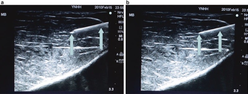
Fig. 18 Bevel up vs. bevel down or bevel at the side (a, b). The bevel up position provides improved visualization of the needle tip because the ultrasound beam is maximally reflected in this position. Panel (a) shows a bright needle tip when the needle is in bevel up position (arrow). Panel (b) shows the exact same needle rotated to bevel down position and demonstrates worsened visualization of the needle tip (arrow).
There has also been a marked and increased echogenicity achieved by creating dents or larger irregularities in only the needle tip and sparing of the procedure needle shaft. The placement or incorporation of these notches in procedure needle tips is created in a fashion similar to that of the design for increased texture needle technology described above. These notched tip procedure needles act to highlight the needle tip echogenicity from the remainder of the needle shaft, and as a result, the needle tip is more visible under ultrasound imaging (Fig. 19).
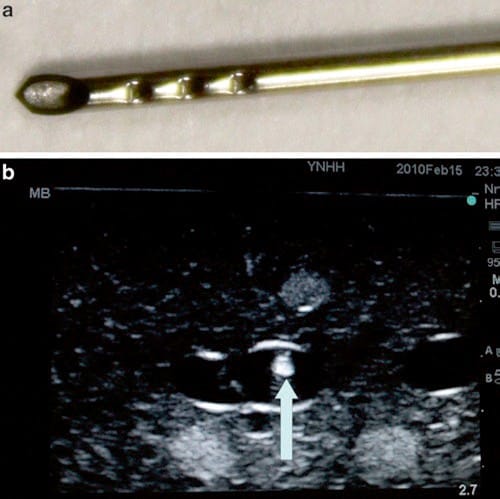
Fig. 19 Echogenic tip. This Havels echogenic tip needle utilizes grooves in the needle tip to improve needle tip echogenicity. Panel (a) shows the Havels needle with grooves in the distal needle tip. Panel (b) shows the highly echogenic needle tip within an ultrasound phantom (arrow). Blue Phantom.
Superior needle tip image quality design and needle shaft image visibility are the factors to be considered for an ideal procedure needle for nerve blocks and UGIP techniques. Another factor that is paramount for an ideal UGIP needle would be its versatility. The UGIP needle should be useable for all types of tissue, be easily visualized at any angle, maintain a sharp depiction of the needle rim, produce low artifact formation without shadowing, and contain qualities that maintain good detection and differentiation from the surrounding tissues and structures. Many of the currently used echogenic needles tested are still far from an ideal echogenic design. However, recent technological advances are rapidly closing the gap between the current echogenic needle design and the ideal echogenic needle to be used during regional anesthesia and UGIP procedures.
10. THE ULTRASOUND DEVICE AND PROCEDURE NEEDLE VISIBILITY
Ultrasound Imaging Artifacts and Procedure Needle Visibility
Ultrasound imaging of needle visibility depends not only upon the properties of the procedure needle used but also upon the technology and capabilities of both ultrasound transducer and ultrasound machine. The ultrasound probe image resolution that results during an ultrasound examination is dependent on the piezoelectric crystal density of the scan head, its crystal type, and the transducer’s receiver properties. Ultrasound image resolution is also dependent upon the power of the ultrasound machine image processor. Advances in both ultrasound transducers and ultrasound image processor technologies continue to assist the practitioner in procedure needle visualization; however, it is imperative that the practitioner gains knowledge of potential artifacts from needle imaging and experience in its interpretation.
Sonographic artifacts related to acquiring and processing of the image by an ultrasound machine may impair both tissue structures and procedure needle visibility in various ways. In some cases, a hyperechoic target may appear hypoechoic or anechoic when the returning ultrasound sound waves are degraded, which can be an effect of acoustic beam misalignment and is termed anisotropy. Anisotropy can be secondary to aberrant reflection and/or refraction (described below) and remains independent of operator acoustic beam misalignment. Reflection from a smooth surface, such as a procedure needle, is termed specular reflection. Reflection from an irregular surface can cause dispersion of the ultrasound beam with subsequent degradation of the received ultrasound signal, which is termed scattering (Fig. 20). Scattering can cause image degradation and artifact; however, scattering may be used to an advantage with the newer developed echogenic procedure needles. When multiple surfaces reflect an ultrasound acoustic beam between each other and the ultrasound transducer, it is termed reverberation (Fig. 21). If ultrasound sound waves are deviated from its path of the incident and then reflected from a deeper structure, it is termed refraction. Attenuation is another factor that can cause ultrasound acoustic beam degradation. Attenuation is described as a decrease in ultrasound signal strength or amplitude as it passes through certain tissue types and can be caused by many of the above-listed factors including reflection, refraction, and scattering. The additive or distorting effects of attenuation, aberrant reflections, and less so with refraction can distort the displayed ultrasound image and may lead to an inability to correctly identify both the procedure needle and surrounding anatomical structures as well as needle proximity to other tissue structures.
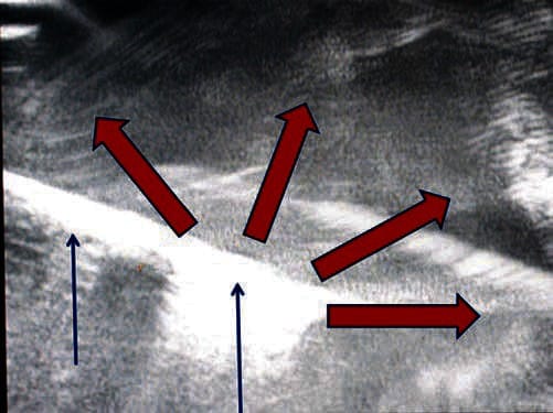
Fig. 20 Scattering decreases needle visibility. Needle scatter can decrease the visualization of needle. The red arrows represent ultrasound beam scatter, which can cause artifact and worsen needle (blue arrows) visualization. Here the needle is inserted in a water bath.
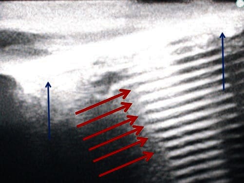
Fig. 21 Reverberation decreases needle visibility. Reverberation can cause reflection of the needle off the structures below and can impair needle visualization. Here the needle (blue arrows) is placed in a surgical gel pad phantom, and there is a clear artifact termed reverberation (red arrows). Surgical gel phantom.
11. IMPACT OF VARIOUS SONOGRAPHIC MODES ON PROCEDURE NEEDLE VISIBILITY
Compound Spatial and Frequency Image Reconstruction Following Acoustic Beam Steering and Variable Frequency
A commonly used solution to overcome the problem of deflection created by an ultrasound signal reflected from a procedure needle is to use a beam-steering sonographic system that enables the production of compound spatial imaging. Beam steering ultrasound systems essentially steer the acoustic beam reflected away from the procedure needle back to the ultrasound probe by altering the internal ultrasound beam angle of incidence (Fig. 22). Older ultrasound probes are limited to mechanical steering, but the newer modern sonographic machines, with broad bandwidth transducers, have specific functions that can change the transmit focus. Broad bandwidth transducers permit the ultrasound probe to produce and accept ultrasound signals at different angles in automatic mode that can produce an improved sonographic image.
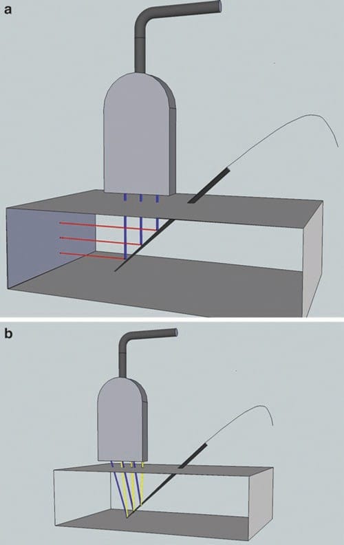
Fig. 22 Beam steering may improve needle visibility. Beam steering improves needle visualization by increasing the angle of incidence between probe and needle and therefore increasing needle visibility. On panel (a) the beam is not steered toward the needle, and fewer of the ultrasound beams in blue are reflected, in red, back to the transducer. On the panel (b) the ultrasound beams in blue are steered toward the needle and reflected back in yellow.
Compound spatial imaging is achieved by the computational process. This is performed by mechanical beam steering that then combines three of more frames from different steering angles into a single frame. Compound spatial imaging allows greater clarity, resolution, and better procedure needle contour definition.
Frequency compound sonography obtains scans from several different frequencies, producing variable speckle artifact patterns in each frame. The frames produced are then averaged, which reduces the speckle and grainy appearance observed in conventional sonography. This result is an improved anatomical ultrasound image of tissue structures, but not a procedure needle imaging quality enhancement.
12. FREQUENCY OF THE ULTRASOUND PROBE (AKA DEPTH) ACOUSTIC POWER AND GAIN
The ultrasound probe most commonly used during UGIP is a 5–10-MHz frequency transducer. This particular ultrasound scan head frequency is known to provide good spatial resolution for nerves and nerve plexus at 1–5 cm depth. A lower frequency, 2–5 MHz, ultrasound probe is often used to visualize deeper nerve and nerve plexus structures. However, the resolution of both anatomical structures and the procedure needle becomes less definitive at increasing depth and the use of lower-frequency ultrasound transducers. The higher-frequency ultrasound probe, with transducer frequencies of up to 18 MHz, is most often used for interventions on the most superficial structures such as nerves of the hand and forearm. Ultrasound device controls that can adjust depth, acoustic power, and gain will permit an option(s) to focus the ultrasound beam to an optimal level and provide an improved ultrasound image. However, this adjustment potential of the ultrasound machine may have only a limited impact on procedure needle visibility outside of its regular optimization of the sonographic image.
13. TIME GAIN COMPENSATION AND HARMONIC IMAGING
Time gain compensation control options on an ultrasound machine will permit adjusting image brightness at variable depths. In addition, changes and adjustments made in gain compensation may minimize many of the sonographic artifacts produced when the ultrasound acoustic beam travels through the skin and other superficial layers. The time gain compensation control option may not only reduce noise produced by tissue artifacts but can also reduce artifact from the paramount signal of the procedure needle.
Another function of the more modern ultrasound devices is harmonic imaging. This function provides the ability to suppress reverberation and several other types of noise artifact produced by skin and body wall structures. Harmonic imaging technology is based on an understanding that body tissues produces a weak but a usable harmonic signal that can be detected and amplified by the sonographic unit. Harmonic imaging capability then uses these detected harmonic signals and applies low-frequency high-amplitude noise that can be used to improve an ultrasound image. The reports resulting from harmonic imaging of procedure needle visualization are mixed and vary from superior ultrasound imaging to procedure needle images that are considered inferior when compared with a conventional ultrasound device without harmonic imaging capability. The impact of the new type of harmonic imaging, broadband techniques, is to be explored.
14. BRIGHTNESS, MOTION, AND DOPPLER MODES
Conventional B-mode (B stands for brightness) serves as the currently used gray-scale sonographic device modality, typically used when performing UGIP. M-mode (M stands of motion) ultrasound machines are used to evaluate the movement of structures within the body. Typically, modern ultrasound machines display the M-mode image adjacent to a smaller version of the original B-mode image on the display screen. When using 2D ultrasound devices, M-mode is focused on the targeted structure and will display its movement over time in the form of an undulating line that is altered according to the moving tissue structures. M-mode has limited use during UGIP, and it does not affect or improve upon procedure needle visibility.
A third imaging modality equipped in modern ultrasound machines is the Doppler mode, comprised of Doppler sensitivity and power Doppler. Doppler mode capability can differentiate blood flow in blood vessels from other similar looking tissue structures and can be utilized to theoretically prevent unintentional vessel penetration or trauma by a procedure needle since the blood vessel can be identified (Fig. 23). Doppler capabilities may also be used to enhance procedure needle imaging quality and clarity in conjunction with other methods and tools described in the “enhancement” section.
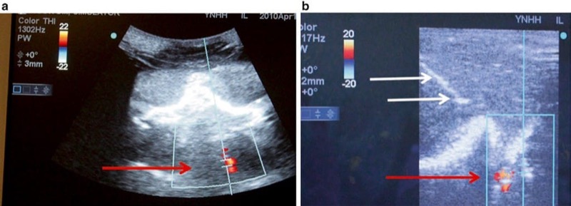
Fig. 23 Doppler may help to prevent inadvertent vessel penetration or intravascular injection (a, b). Using Doppler can assist in the visualization of vessels to be avoided when undergoing ultrasound-guided procedures. Panel (a) shows the detection of blood flow with Doppler in the vertebral artery (red arrow) at the level of cervical spine C7 in a prone position. Panel (b) shows a needle (white arrows) avoiding the prior identified vessel (red arrow) on Doppler ultrasound in a lateral position. Combined ultrasound and fluoroscopic phantom for cervical transforaminal injections
15. 3D AND 4D ULTRASOUND IMAGING
Typical 2D ultrasound imaging captures and displays a flat ultrasound image in two planes and is analogous or similar to current fluoroscopy. 3D ultrasound technology captures images in multiple planes and at different angles. The resulting 3D ultrasound image can then be displayed in a 3D representation or schema of scanned structures. Advantages of static 3D imaging are described by Clendenen et al. when comparing differences between plain radiographic imaging (analogous to 2D sonography) and conventional computer tomography (analogous to static 3D ultrasound imaging). 3D ultrasound imaging in real time (dynamic 3D and sometimes termed as 4D imaging) adds time as a fourth axis to traditional X, Y, and Z dimensions. Dynamic 3D imaging (4D) allows for real-time tracking of an intervention that is comparable to real-time CT or MRI technologies, but with levels of simplicity, safety, and cost which are difficult to compare. Current 4D ultrasound technology has limitations related to scanning and visibility of superficial interventions that is based on the same current limitations that are associated with 3D ultrasound probe frequency. However, we have recently witnessed significant improvements in ultrasound technology and anticipate that such technology will continue to rapidly improve.
Initially, 3D ultrasound imaging was produced by a freehand move of the regular 2D ultrasound probe over the skin. This maneuver was then followed by a reconstruction procedure that is similar to one used in computed tomography, but is cumbersome and time intensive. Despite the introduction of special 2D transducers fitted with a rotating receiver inside the ultrasound probe and providing excellent biplane and multiplane 3D images, the image reproduction is static and not imaged in real time. With 4D ultrasound imaging, there is a small but noticeable lag in the real-time 3D image of the procedure needle. In addition, there have been no obvious benefits reported in terms of better procedure needle visualization with the special 2D ultrasound transducers, and these transducers are cumbersome for UGIP purposes.
Current technological limitations of 3D ultrasound transducers are derived from the difficulty in producing small and maneuverable ultrasound probes that are capable of housing the necessary and advanced scanning mechanical machinery (Fig. 24). However, real-time tracking of procedure needles with these types of ultrasound transducers could be potentially superior to images produced by current sonographic technologies, especially in experienced hands (Fig. 25).
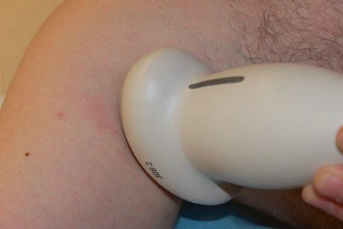
Fig. 24 3D needle ultrasound and needle visibility. This is a 3D ultrasound probe. Currently 3D ultrasound probes are larger than their 2D counterparts. However, newer, smaller 3D ultrasound probes are in development.
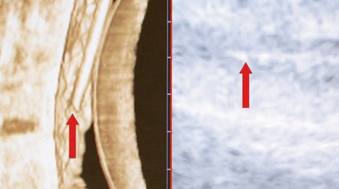
Fig. 25 3D image of the needle in the phantom. Here, a needle is visualized within an ultrasound phantom under 3D ultrasound in real time, also termed 4D ultrasound. The needle is clearly visualized in 3D on the left (left red arrow) and is less visible under conventional ultrasound on the right (right red arrow).
Another recent advance in 3D ultrasound technology is the matrix array transducer. Creation of 3D and 4D ultrasound images has been developed independent of the mechanically steered array ultrasound probe with the use of a matrix array transducer. These probes are smaller and lighter and have better ergonomic profiles. The development of matrix array ultrasound transducers has resulted in smaller transducers while also increasing speed of data acquisition and processing by roughly three times faster than a conventional mechanically steered array ultrasound transducer. This translates into a true 4D experience and could lead to improved transducer maneuverability and procedure needle visualization.
16. RECENT ADVANCES IN ULTRASOUND IMAGING AND PROCEDURE NEEDLE VISIBILITY
Complex signal processing, broadband transducers, increased scanner bandwidth, upgradable software, and other recent technological developments have made investigational improvements in ultrasound image quality. Increasing ultrasound beam frequency of sonographic systems up to 50 MHz could lead to improved image quality, especially when the UGIP target structures are superficial or during UGIP in the pediatric patient population. Combining ultrasound with other imaging technologies including fluoroscopy, computed tomography, and magnetic resonance imaging may represent a high-yield strategy for better localization of procedure needles during an UGIP intervention. One of the newest dual imaging systems currently being developed is a photoacoustic and ultrasound imaging combination. These advances along with other technologies in sonographic imaging are in transition from research to possible clinical implementation, and the impact of these technologies on procedure needle visibility is yet to be determined.
To obtain optimal procedure needle sonographic image visibility, it is first important to acquire manual dexterity, apply the advanced ultrasound technologies, and maintain experienced needle/ultrasound transducer manipulations. Additional measures to assist in providing improved procedural needle visualization are automatic optimization technologies of the ultrasound image that have been developed and are available on modern ultrasound machines. These automatic optimization technologies permit the practitioner to choose between preset modes optimized to visualize certain tissues and structures such as vascular, muscular, breast, and others. Recent advances in sonographic border detection have resulted in technology that can identify and assume automatic color marking of nerves (yellow), muscles (brown), arteries (red), and veins (blue) and will possibly be available in the near future.
Incorporation of UGIP systems into the Internet network may provide specific clinical benefits by permitting real-time online consultations by pain management specialists, target structure imaging enhancement suggestions, procedure needle visualization assistance, and confirmation provided by experienced ultrasound practitioners. However, image optimization of sonographic target structures does not automatically provide adequate procedure needle visibility. Even despite the many advances made toward ultrasound imaging technological improvements, it has not always translated into better procedure needle visualization. One probable explanation for the dissociation between targeted structure ultrasound imaging optimization and advances toward procedure needle visualization improvement is that traditional application of ultrasound in medicine is typically focused on imaging and diagnosis. Although there continues to be some efforts achieved and attempts made to improve upon sonographic systems so that they may be adjusted to permit interventional instruments and procedure needles to produce more optimal visibility under ultrasound imaging. Unfortunately, such systems have usually been limited toward improving upon sonographic visualization of surgical instruments or computer-assisted imaging units and development of robotic systems for UGIP. The advancements in ultrasound technology and improvement in development of procedure needles for UGIP seem to be somewhat disconnected, possibly due to the narrow specialization of procedure needles and ultrasound machine manufacturers. However, this gap has recently been reduced due to the fact that there are a growing number of improved procedure needles and UGIP being developed across several different fields of medicine. There have been advances in developing technology that can diminish sonographic artifacts produced by the gas of radiofrequency ablation and those created during interventions associated with cryoablation that remain pertinent to pain medicine.
There are reasons to believe that a concerted coordination of effort toward procedure needle and sonographic equipment manufacturers to improve upon needle visibility for UGIP interventions is underway. Such development efforts will likely translate into an association with sonographic technology designed specifically for the growing field of interventional pain medicine and may represent a promising, practical, scientific, and business niche for the specialty. The current important issue that remains a crucial variable is the need to develop further technology that will improve upon consistently securing appropriate alignment of the procedure needle with the ultrasound transducer. This continues as one of the important aspects of UGIP and interventional pain medicine that, if mastered, will in the end produce a successful interventional procedure for the patient.
17. NEEDLE-PROBE ALIGNMENT
Need for Procedure Needle and Ultrasound Probe Alignment
A typical ultrasound beam width that is emitted from an ultrasound probe is only about 1 mm (Fig. 26). Therefore, imaging a procedure needle can often be complicated as a result of misalignment of the ultrasound beam and the needle during an “in-plane” technique of regional anesthesia and UGIP procedures. It remains relatively easy for the procedure needle to deviate from under the narrow ultrasound beam, so diligence remains necessary as even small movements of the ultrasound probe or needle will result in the loss of the procedure needle image on the ultrasound screen. As a result of an inability to maintain the ultrasound image of a procedure needle, both regional anesthesia and UGIP techniques may lead to prolonged procedure times or result in an increased complication rate due to unintentional tissue and structural damage. Therefore, successful ultrasound procedure needle visualization remains important, and careful needle positioning, advancement, and manipulation in relation to the ultrasound probe are of critical importance.
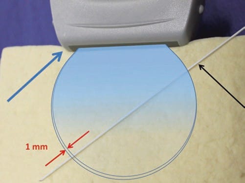
Fig. 26 The need for alignment. The ultrasound probe (blue arrow) emits a very narrow beam (rounded shape) close to 1 mm width (red arrows) which widens with distance from the probe. This small area can make it difficult to visualize the needle (black arrow) if it is misaligned. Tofu phantom.
18. “IN-PLANE” AND “OUT-OF-PLANE” NEEDLE APPROACH: CLASSICAL PROBE-NEEDLE INTERPOSITIONS
Several strategies have been suggested for procedure needle ultrasound visualization and imaging, yet there are two classical techniques known as the “in-plane” (IP) approach and the “out-of-plane” probe footprint. The IP approach is based on a concept of procedure needle visualization as a hyperechoic bright line. The OOP approach is achieved by inserting the needle under, midline, (usually) and perpendicular to the ultrasound probe footprint in a short axis to the ultrasound beam where the needle tip/shaft appears as a bright hyperechoic dot (Fig. 27).
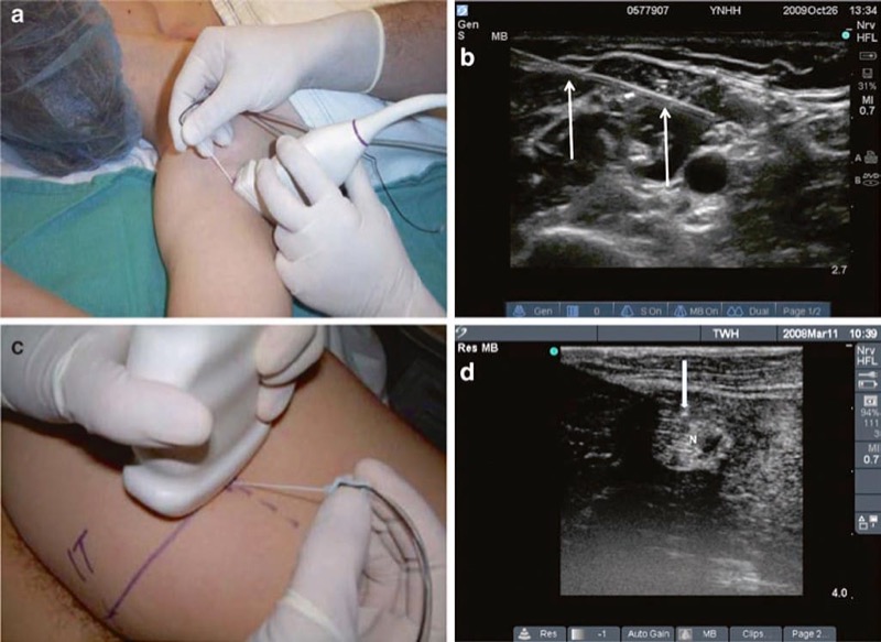
Fig. 27 In-plane (IP) and out-of-plane (OOP) techniques. This is the in-plane technique. The needle is held inserted parallel to the probe (a) and is seen (white arrows) in the long axis on ultrasound (b). The out-of-plane technique is demonstrated in panel (c). The out-of-plane approach is achieved by inserting the needle in the short axis of the beam, and therefore the needle tip (white arrow) appears as a bright hyperechoic dot (d). N sciatic nerve above popliteal fossa.
An identified disadvantage of the IP approach that is often cited is that the procedure needle can more easily deviate away from the narrow ultrasound beam and result in or cause potential complications and lengthen block procedure time if the needle cannot be imaged throughout the selected pain management intervention. Another potential disadvantage of the IP approach is the associated reverberation created from the long axis of the needle shaft that may impair detection of structures below the imaged procedure needle shaft. A disadvantage of the OOP approach is associated with an inability or increased difficulty to accurately follow the procedure needle to the selected target. Another complication associated with the OOP technique is lack of assurance or inability to confirm whether the hyperechoic dot seen on the ultrasound image is an approximation of the procedure needle tip or an approximation of the needle shaft. An important consideration when comparing or selecting between the two techniques (IP or OOP) is that the IP approach requires two to three times more needle length insertion to reach the desired target when compared to the OOP approach along with the associated potential to create additional patient discomfort. It remains clear that there are some drawbacks to both IP and OOP procedure needle approaches when performing regional anesthesia and UGIP. Therefore, gaining experience with both approaches is necessary in order to select the most appropriate technique for each particular procedure. As an additional alternative, the oblique plane approach is yet another technique that may be considered when selecting ultrasound-guided pain management in a search to minimize or eliminate some of the drawbacks from either an IP or OOP approach for procedure needle visualization.
19. OBLIQUE PLANE NEEDLE APPROACH FOR ULTRASOUND-GUIDED PAIN MANAGEMENT
The oblique plane approach is achieved by viewing the target anatomical structures (including nerves and vessels) in the short axis and places the procedure needle in long axis to the ultrasound probe. This approach permits the operator to obtain an optimal view of the underlying target and surrounding structures while maintaining continuous visualization of procedure needle and needle shaft during movement and manipulation (Fig. 28). The oblique plane approach has been found to be useful in certain procedures where the target nerve may be traditionally difficult to visualize. As an example of such a situation, the femoral nerve (lateral and inferior to the femoral artery) typically has a fattened shape as it is wedged between the iliacus muscle and hyperechoic fascia that may lead to some degree of obstruction of an optimal sonographic view. The oblique approach often retains the advantages of the OOP technique while enabling a clearer view of the procedure needle shaft and tip during advancement.
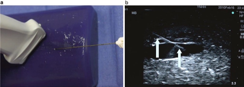
Fig. 28 The oblique plane technique (a, b). The oblique plane approach is achieved by viewing the short-axis view to visualize the target anatomical structures including nerves and vessels but places the needle in long axis to the probe. Panel (a) shows the needle and probe positioning for the oblique view. Panel (b) shows the image of the needle (arrows) on ultrasound in the oblique view. Blue Phantom.
20. BIPLANE NEEDLE IMAGING APPROACH FOR ULTRASOUND-GUIDED PAIN MANAGEMENT
Some of the 2D ultrasound units and machines with 3D capabilities permit combining images in different planes (in “real time”) on the same ultrasound screen. This allows the practitioner to observe both anatomical structures and the needle in two or more planes simultaneously. For example, a vessel could be viewed in either long axis or a transverse axis at the same time on a split ultrasound screen display. A biplane transducer is used for 2D ultrasound, and 3D ultrasound probes produce multiplane images. Both bi- and multiplane imaging techniques may have great potential for improving needle visualization and UGIP procedures, but as the technology is still relatively new, its utility has yet to be established. However, the biplane imaging capabilities are unlikely to replace the cornerstone techniques of basic procedure needle and transducer alignment, which greatly improve needle tip and shaft visibility.
21. MECHANICAL AND OPTICAL PROCEDURE NEEDLE GUIDES
The importance of procedure needle alignment with the ultrasound probe beam has prompted the consideration and development of various types of guides for needle stabilization and for needle path direction. These procedure needle guides are intended for alignment and synchronization of the needle with the ultrasound transducer probe position and essentially keep the needle path under the ultrasound beam. Several types of procedure needle guides have been described such as the mechanical needle guide that is a device attached directly to the ultrasound probe and used for aligning the procedure needle so its trajectory remains under the ultrasound beam. Such procedure needle guide devices are designed to match with specific types of ultrasound probes and with the intent that as the procedure needle is being advanced, it will be directed in a path under the ultrasound beam (Fig. 29). Initially, these types of guide devices were introduced into clinical practice for the performance of biopsies, and the guide devices helped to facilitate procedures performed by less experienced practitioners. The developed ultrasound guide procedure needle devices are routinely mentioned in the literature as it describes techniques for optimizing needle visualization under ultrasound for regional anesthesia.
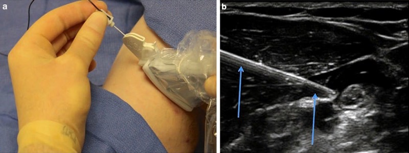
Fig. 29 Mechanical needle guides (a, b). Mechanical needle guides can improve needle visibility significantly by stabilizing both transducer and needle. Panel (a) shows the CIVCO mechanical needle guide. Panel (b) shows the needle (arrows) under mechanical guidance.
Mechanical needle guidance has shown to significantly (2×) reduce the time necessary to safely perform UGIP procedures. Use of such devices has also demonstrated superior needle visualization when tested by inexperienced residents performing simulated UGIP procedures on porcine phantoms. Needle visibility proved to be approximately 30% better with the use of mechanical procedure needle guide devices, and trainees ranked their satisfaction with needle guidance devices significantly better than “freehand” techniques. However, the routine performance of UGIP typically requires frequent adjustments in needle path direction(s) that could be a potential drawback of a rigid mechanical guide device. It may not be easy to achieve optimal visualization of surrounding tissue, nerve target structures, and procedure needle direction with use of a rigid mechanical needle guide device since it is often necessary and required that dynamic needle adjustments are performed during UGIP. Therefore, the role of rigid mechanical needle guide devices for facilitation of procedure needle visualization during pain management interventions and procedures is still yet undetermined.
Adjustable mechanical needle guide devices have been developed and trialed in order to overcome the drawbacks of rigid mechanical devices. Various types of mechanical devices to guide procedure needles have created a basis and prompted the production of robotic-guided UGIP systems. However, practical applications of robot-guided approaches for UGIP currently appear to be limited. A potential solution for the shortcomings of the various needle guide devices was developed and described by Tsui by means of a laser system-based device. The laser guide device is designed to facilitate UGIP needle and ultrasound probe alignment. This optical procedure needle guide is comprised of a laser beam allowing easy adjustment of the procedure needle position as needed (Fig. 30). It has been determined that this optical needle guide provides an unambiguous visual trace of accurate needle-beam alignment and may therefore be useful in teaching and developing bimanual coordination for trainees. Longer procedure needles are typically necessary when using this laser device since a larger portion of the procedure needle shaft should protrude from the skin during the UGIP procedure so as to permit alignment of the needle and laser beam.
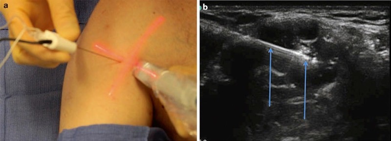
Fig. 30 Optical needle guide (a, b). The Tsui device enhances needle visualization by improving alignment. Panel (a) shows the Tsui device clearly demarcating the angle of entry and the needles in relation to the probe with the light beam (red). Panel (b) shows the needle (arrows) insertion under the optic guide guidance.
22. ADVANCED PROCEDURE NEEDLE POSITIONING SYSTEMS
Most experienced practitioners who use ultrasound prefer to perform UGIP using “freehand” techniques in which the operator can freely manipulate the ultrasound transducer with one hand and procedure needle with the other hand. The freehand technique affords flexibility in positioning the procedure needle during its placement and advancement toward the targeted structure(s). Even for an experienced practitioner, it can sometimes be difficult to maintain both the needle and target in view while avoiding various tissue structures, blood vessels, and other nerve structures.
One potential solution toward improving a practitioner’s guide of predicting a procedure needle trajectory is an advanced positioning system that uses optical or electromagnetic tracking systems. This particular tracking system uses a sensor attached to an ultrasound probe and another sensor attached to the procedure needle’s hub. This device uses an electromagnetic tracking system and performs calculations that can predict procedure needle trajectory that is then extrapolated and displayed (on the screen) as an estimation of a procedure needle anticipated path.
The initial developments for the electromagnetic tracking system were described as separate units that were designed to acquire ultrasound images from conventional ultrasound machines that have an output port. This kind of positioning system would recreate sonographic images obtained from the ultrasound machine and combine this actual image with predicted needle path on the separate screen. The latest technology permits incorporating advanced positioning systems into current ultrasound machines (Fig. 31). Most sonographic equipment manufacturers are actively developing this particular type of technology for advanced positioning procedures that are to be used in UGIP for 2D, 3D, and 4D systems. Combined ultrasound and CAT scan or ultrasound and MRI radiofrequency ablations along with other pain medicine interventions may employ advanced interventional tool positioning systems in the near future.
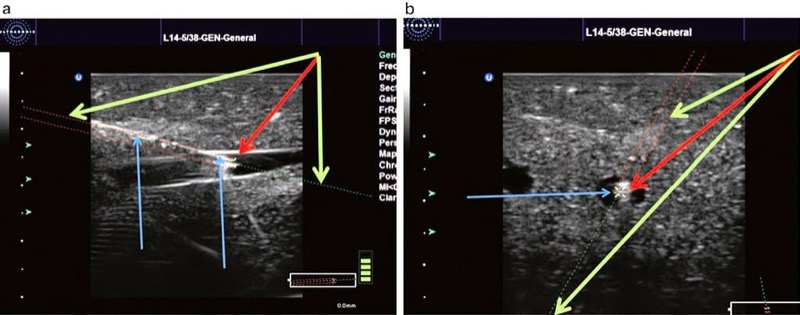
Fig. 31 Ultrasound (US) advanced positioning systems (a, b). US advance positioning systems use optical or electromagnetic tracking technologies that calculate the needle projection which is then displayed as a prediction of needles future path on the screen. Panel (a) shows the needle in an in oblique plane approach (blue arrow + green arrow) and extrapolates the direction of the needle shown by the dotted green line. The tip of the needle is marked by device red arrow. Panel (b) shows the needle in an out-of-plane approach and again extrapolates the direction of the needle (blue arrow) shown by a dotted green line (green arrow). Again, the needle tip is marked by device (red arrow). Ultrasound GPS, used with permission of Ultrasonix. Blue Phantom.
23. THE “ART” OF SCANNING FOR BETTER PROCEDURE NEEDLE VISUALIZATION
Advances in needle positioning systems that permit UGIP to become more efficient, interactive, safe, and objective such that it will likely compensate for some of the current difficulties and shortcomings in learning UGIP will continue to develop. However, it is unlikely that such a positioning system will replace currently practiced needle-transducer alignment skills as they will remain an integral part of UGIP performance. Marhofer and Chan described various movements of the ultrasound transducer that can improve procedure needle tip visualization, and they emphasize that such movements of the transducer and needle should be deliberate and slow. Marhofer and Chan further emphasize that the practitioner move or manipulate only one part of the system at a time (i.e., only move the ultrasound transducer or the needle to optimize procedure needle tip visualization). These slow and deliberate movements should be kept separate or independent from one another (move either needle or probe) in order to minimize repositioning steps or maneuvers (probe sliding, tilting, rotating) that may prolong UGIP performance. The chapter continues to describe the “ART” of ultrasound scanning techniques as a useful tool for effective ultrasound transducer movements where (1) sliding is referred to as alignment (A), either in plane or out of plane as the transducer slides on the skin surface, (2) rotation (R) refers to clockwise and counter clockwise movement of the ultrasound transducer, and (3) tilting (T) refers to angling the transducer to maximize the ultrasound beam signal to maintain as best as possible an angle of incidence at 90° (Fig. 32).
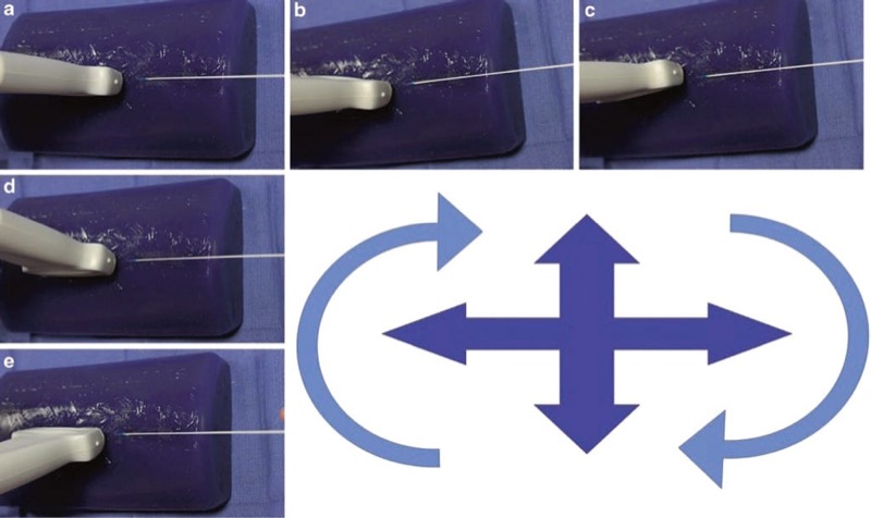
Fig. 32 Probe and needle alignment by rotation, sliding, and tilting. Probe and needle alignment by rotation, sliding, and tilting are all important factors in successful needle visualization. Panel (a) shows the probe and needle aligned in the in-plane technique. Panels (b) and (c) rotate the probe clockwise and counterclockwise. Panels (d) and (e) tilt the probe forward and back. Blue Phantom.
24. ERGONOMICS FOR BETTER PROCEDURE NEEDLE VISIBILITY
Unintentional or nondeliberate ultrasound probe movement was found to be the second most common error performed by trainees during regional anesthesia and UGIP procedures. A satisfactory ultrasound image of target structures (e.g., nerve) and procedure needle could be easily and quickly lost with even minor or small manipulations (sliding) of the ultrasound probe that has been prepared (placed in ultrasound gel) for regional anesthesia and UGIP. These seemingly minor or small ultrasound probe movements, caused commonly during attempts to reach for supplies or poor ergonomics, for example, are errors that must be considered to avoid prolonging UGIP procedure performance. Sites et al. demonstrated that novice practitioners created errors (approximately 10%) that comprised of poor ergonomics and operator fatigue. Operator fatigue during UGIP typically presented as the need to switch hands holding the ultrasound probe during the performance of a procedure, the need for use of both hands on the ultrasound probe, and hand tremors or shaking. These fatigue issues and small or minor ultrasound probe movements may potentially further compromise procedure needle visualization as well as UGIP efficiency and success.
In order to overcome some issues compromising UGIP success, the ultrasound probe should be manipulated, and measures should be taken to properly stabilize ultrasound probe positioning while also taking steps to minimize operator fatigue. To improve ultrasound probe stabilization techniques, the operator should use freehand techniques during UGIP procedures. Freehand techniques are performed by having the operator’s ultrasound transducer hand function as both ultrasound transducer stabilizer and for localizing and maintaining the target structure on the ultrasound image screen. The practitioner may also consider using the resting fingers of the hand used to hold the ultrasound probe to apply pressure downward which may minimize probe movement and reduce operator fatigue (Fig. 33). The freehand technique may also lessen slipping of the ultrasound probe on the gel-covered skin surface.
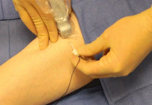
Fig. 33 Freehand technique. Freehand techniques are performed by having the operator’s ultrasound transducer hand function as both ultrasound transducer stabilizer and for localizing and maintaining the target structure on the ultrasound image screen. The practitioner may also consider using the resting fingers of the hand used to hold the ultrasound probe to apply pressure downward which may minimize probe movement and reduce operator fatigue. The technique may also lessen slipping of the ultrasound probe on the gel covered skin surface.
When performing UGIP procedures, it is always useful to do a preprocedural ultrasound scan of targeted structures and surrounding tissue area and then mark or identify (on the patients skin) optimal probe position outlining the ultrasound probe footprint positioned where the most ideal target image is best visualized. This quick, easy, and beneficial measure may minimize or avoid excessive ultrasound probe and needle movements during UGIP intervention that could translate into inefficient and time-consuming UGIP procedures as well as possible unintentional structural damage (Fig. 34). To further optimize procedure needle ultrasound visualization and decrease operator fatigue, simple measures should be taken to improve practitioner ergonomics. Some simple measures to improve operator ergonomics are to prepare all the necessary supplies before the ultrasound probe is prepared and placed in a sterile sheath as well as raising the patient’s bed height to maintain proper operator posture. To further improve procedure needle and ultrasound probe alignment, in addition to decreasing operator fatigue, there are special carts designed for UGIP, ultrasound adhesive gels, and stabilizing mechanical arms to minimize ultrasound transducer movements (Fig. 34).
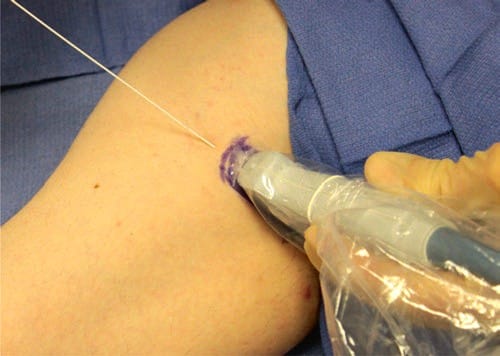
Fig. 34 Marking of the skin. Marking of the patient skin site affords the operator improved alignment. This is especially true in cases of patient movement or loss of prior probe needle alignment.
25. ENHANCEMENT AND TECHNIQUES TO IMPROVE PROCEDURE NEEDLE LOCALIZATION
Basic Sonographic Effect of Enhancement
Enhancement is the description of what occurs and what is seen on an ultrasound image when tissue with low acoustic impedance, such as blood within a vascular structure, enhances its containing vessel wall as an ultrasound signal which makes it appear hyperechoic. Similarly, the concept of enhancement may also improve the visualization of a procedure needle within a vascular structure or certain tissues (e.g., fat) that have lower acoustic impedance when compared to the needle (Fig. 35).
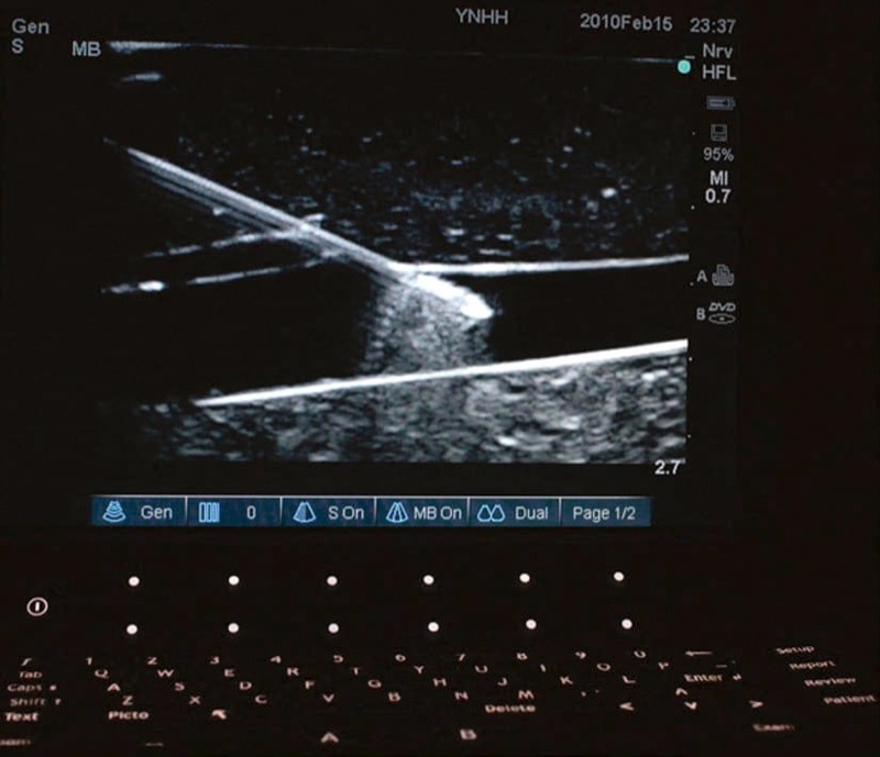
Fig. 35 Needle enhancement. Needle enhancement within the vessel wall occurs because of an increased difference in acoustic impedance between needle and vessel fluid. The needle shaft at the site of entry into the vessel wall does not enhance as brightly as the tip within the vessel wall.
An understanding and application of the enhancement concept could provide value in situations in which procedure needle localization and tracking may prove to be difficult during UGIP procedures. Despite the use of echogenic procedure needles and advanced sonographic technology along with skilled and experienced needle and ultrasound probe manipulation, performing UGIP in all situations may not be enough to be successful with the proposed intervention. Application of the useful strategy of enhancement and other techniques described below may prove beneficial toward highlighting procedure needle localization under ultrasound.
26. ENHANCEMENT WITH PRIMING, INSERTION OF STYLET OR GUIDE WIRE, AND VIBRATION
There are instances in which the procedure needle may prove difficult to visualize despite correct procedure needle and ultrasound transducer alignment and positioning. In some of these difficult to maintain needle visualization situations, a procedure needle could be localized, simply by moving the entire needle (or a stylet/guide wire that has been placed in the lumen of the needle). Chapman et al. describes movement of the inserted procedure needle in short “side-to-side” and “in-and-out” motions that deflect adjacent tissues and may improve the visualization of the needle path and trajectory. However, movement of the entire procedure needle may cause additional patient discomfort, and it could result in unintentional tissue structural damage if the needle tip is not visualized.
When continuous ultrasound scanning of procedure needle insertion and passage toward a target structure is not successful, the needle tip may be localized by inserting a small guide wire or stylet through the needle to the needle tip. Chapman et al. describes priming a procedure needle by submersion of the needle in sterile water can cause enhancement of the needle during ultrasound scanning. Another technique that can be used is with the Doppler function of the ultrasound machine to detect procedure needle vibrations. With the color flow Doppler function of the ultrasound device activated, a slightly bent stylet is inserted into the procedure needle and then rotated causing lateral vibration of the needle. This vibration of the needle is detected and visualized by color flow Doppler and may assist in improving procedure needle visibility on the real-time ultrasound screen (Fig. 36). Devices are now commercially available that utilize this principle of vibrating the procedure needle to improve needle visibility. Such technology is used by attaching a small device onto the procedure needle shaft that when activated can produce small vibrations at the needle tip (maximum amplitude 15 mm that are imperceptible to touch) that then generate a signal with color flow Doppler.
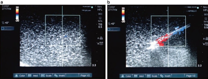
Fig. 36 Improved procedural needle visualization under Doppler ultrasound (a, b). Applying vibration to the needle with a stylet inserted and moved will cause slight needle movement and improve visualization under Doppler ultrasound. Panel (a) shows the needle under ultrasound without vibration. Panel (b) shows color Doppler signal with movement of the needle stylet.
Another approach that may improve procedure needle visualization (while using Doppler) has been accomplished by applying vibratory actions to the tissue around the target structure rather than to the needle. By activating the color flow Doppler option, the ultrasound probe or transducer is being activated to vibrate at various frequencies. Then the amount of tissue vibration that is caused by the ultrasound probe at each of the frequencies is measured by using a quantitative power Doppler algorithm built into the scanner. This advanced ultrasound imaging technique could help to produce better procedure needle localization and may have potential for use in many pain management procedures and interventions.
27. HYDROLOCALIZATION OF THE PROCEDURE NEEDLE
There are several studies that describe injection of a small amount of fluid (0.5–1 ml) through the needle in order to assist in confirming procedure needle tip location or position. This maneuver is usually performed by first moving the inserted procedure needle and observing the movement of the surrounding tissue and then by fluid injection while look ing for the appearance of a small hypoechoic or anechoic pocket at the site of the needle tip created by the injected fluid. Hydrolocalization is the term or name given to this maneuver by Bloc et al.. It can be carried out with sterile water, normal saline, an injection of local anesthetic, or 5% dextrose (Fig. 37). Use of a 5% dextrose solution, in order to preserve motor function and response, is most optimal for combined ultrasound-guided and nerve stimulation techniques during the performance of peripheral nerve blocks.
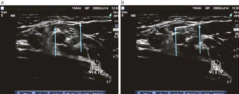
Fig. 37 Hydrolocalization technique (a, b). Hydrolocalization is carried out by injecting the fluid that can improve needle tip visualization by first forming an anechoic pocket which then enhances the needle tip. Panel (a) demonstrated that the procedural needle (right arrow) tip (left arrow) is difficult to visualize. Injection of fluid, shown in panel (b), made the tip (left arrow) of the procedural needle (right arrow) to be easily localized.
28. PROCEDURE NEEDLE VISIBILITY BY AGITATED SOLUTIONS OR WITH ULTRASOUND CONTRAST AGENTS
Similar to hydrolocalization described above, injection of microbubbles uses a small bolus of agitated saline placed through the procedure needle. This technique may assist in ultrasound-guided needle tip visibility and could further improve visualization and localization of both the procedure needle or threaded catheter (Fig. 38). Microbubbles may produce needle enhancement by taking advantage of the acoustic impedance mismatch between injected microbubbles and the surrounding tissues. However, the microbubble injection technique has received some criticism when practicing UGIP as it has the potential disadvantage of creating an acoustic shadow and potentially obscuring the image of target structures.
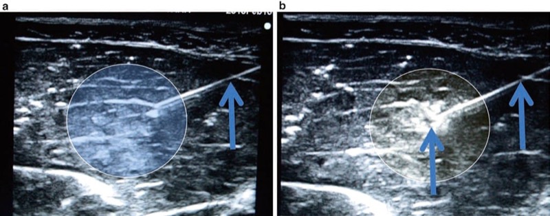
Fig. 38 Microbubble injection technique (a, b). The microbubble injection technique uses a small bolus of agitated saline which is injected through the needle tip and can further improve visualization and localization of the needle. Panel (a) shows the needle prior to injection. Panel (b) shows the needle tip and surrounding area after injection of the microbubbles. Microbubbles can disrupt the visualization of structure deep to the microbubbles seen in panel (b). Porcine phantom.
The microbubbles represent one of the varieties of ultrasound contrast media. The pre-made ultrasound contrast agents are available on the market, and they typically employ encapsulated lipid-based nanoparticles or polymeric micelles. These injectable contrast agents can significantly increase the amount of ultrasound backscatter imaging, and this may improve procedure needle visibility under conventional ultrasound or color flow Doppler. The disadvantages of injecting contrast agents are the costs associated with the agents as they are expensive and they require an additional intravenous injection. There are no studies performed describing the use of these contrast agents for improved needle visualization in regional anesthesia or pain medicine, but they may be potentially useful if employed for UGIP procedures. There is an understanding that if ultrasound contrast technology is developed, this technique could become a useful adjunct or tool for improving upon procedure needle tip visualization.
29. LOCALIZATION OF THE PROCEDURE NEEDLE TIP WITH THE AID OF NERVE STIMULATION
It is known that it can sometimes be difficult to determine the proximity of the procedure needle tip in relation to targeted nerve structures on the ultrasound screen. Tsui et al. reported that nerve stimulation can be used to aid in the UGIP training settings and to assist in verifying the position of the needle tip in relation to nerve structures. Chantzi et al. have confirmed that the combined technique using both ultrasound and percutaneous nerve stimulation may serve as a reliable method for procedure needle tip location verification. Combined ultrasound and nerve stimulation techniques by anesthesia residents and practitioners who are not skilled at ultrasound-guided procedures or with little ultrasound experience may be able to improve their skills when attempting to identify nerve structures in situations of difficulty in needle tip localization. UGIP combined with nerve stimulation has been shown to increase the success rate of pain management interventions.
In addition, because procedure needles used during nerve stimulation techniques are polymer-coated, they are by definition echogenic and remain attractive for use with UGIP procedures. One of the drawbacks for this technique is that by combining UGIP and nerve stimulation, it requires the availability of both an ultrasound machine and necessary equipment for neurostimulation that must all be made available in the sterile field. Another potential disadvantage of the combined technique is that nerve stimulation controls and the ultrasound image screen are located on two separate display panels (ultrasound and neurostimulator) that could cause difficulty with visualization and simultaneous calibration on two individual devices. The processes required in setting and changing of device adjustment controls could possibly lead to unintentional procedure needle or ultrasound probe movement. A potential solution for this problem would be an ultrasound machine that also has the ability of incorporating the mechanics of a nerve stimulator. Therefore, when stimulating procedure needles and perineural catheters to confirm anatomical locations and proximity to target sites during nerve block techniques, there would be added benefits of both adjunctive ultrasonography and nerve stimulation that could be controlled simultaneously. In addition, when both, the needle and target, are adequately imaged, the nerve stimulation as an adjunct to ultrasound guidance may have a limited role because a positive motor response to nerve stimulation does not increase the success rate of the block. In addition nerve stimulation when combined with UG does have a high false-negative rate that suggests these blocks are usually effective, even in the absence of a motor response. Potential problems with adequate neurostimulation when used in conjunction with UGIP could be related to the ultrasound gel. When 5% dextrose was used, as a nonconducting medium, it did not affect electrical conduction during electrical stimulation. Thus, it is important to avoid using saline or gel as a sound medium because it may hinder any subsequent attempts to electrically stimulate the nerve.
30. SUMMARY
In order to unmistakably visualize the procedural needle under the ultrasound and manipulate the needle effectively, a new set of skills is to be acquired. These skills are the critical assets which unlikely will ever be substituted by advanced ultrasound technology and enhanced procedural needles. The techniques discussed in this chapter intend to help to improve needle visualization during UGIP. They should be used in combination, depending on the nature and localization of the procedure.