 Nerve Blocks App
 Pain Medicine Assistant App
 POCUS App
 IV Access App
 MSK Knee App
 VetRA App
 Nerve Block Manual
 Regional Anesthesia Updates
 Anesthesiology Manual
 Anesthesiology Review
 Anesthesia Updates 2025
 Anesthesia Updates 2026
 Pediatric Anesthesia Updates
 Airway Management Updates
 US Interventional Pain Manual
 Pain Medicine Updates
 Mastering Difficult IV Access
 PACU Nursing Manual
 RA Veterinary Manual
 About
About
The concept of blocking the spinal nerves is validated by relieving the pain transmitted by that nerve. Similarly, blocking a painful structure (e.g., inflamed joint) should provide at least temporal alleviation of pain. Diagnostic and therapeutic lumbar zygapophysial (facet) nerve and joint interventions are among the most commonly performed injections in pain management. Traditionally, fluoroscopic guidance is required to ensure precise needle positioning and to exclude intravascular injection. Since the procedure is considered to be a low-risk intervention, utilization of ultrasound guidance is thought to be an attractive alternative to fluoroscopy mainly because it renders no ionizing radiation to the patient and medical personnel and helps identify soft tissue targets. In addition, ultrasound-guided procedures are essentially “office-based” and do not require a radiology suite or operating room.
1. ANATOMY
The lumbar vertebrae, L3–L5, are most frequently involved in spinal pathology because these vertebrae carry the majority of body weight and are subject to the largest stress forces along the spine. Each vertebra is connected to the adjacent level by the intervertebral disk anteriorly and the zygapophysial or facet joints in the posterior. The vertebral body is a thin rim of dense cortical bone encompassing the trabecular inner milieu. The pedicles are two short, rounded processes that extend posteriorly from the lateral margin of the dorsal vertebral body. The laminae are two flattened plates of the bone extending medially from the pedicles to form the posterior wall of the vertebral foramen. The ligamentum flavum anchors the posterior wall of each vertebra. As the nerve root exits the foramen, it divides into ventral and dorsal rami. The dorsal ramus gives off three branches, the medial, intermediate, and lateral branches. Each facet joint is innervated by the medial branch at the corresponding level and from the level above. Medial branches travel in the groove formatted by the corresponding superior articular process (SAP) and the transverse process or may lie slightly cephalad at the base of the SAP. The L5 medial branch is an articular nerve network with a variable pathway, and, therefore, the L5 dorsal ramus is targeted. This nerve is constantly located at the root of the S1 SAP and the sacral ala. Anatomic variations of the lumbar spine can pose a challenge during image-guided zygapophysial nerve and joint injection. Variations, including scoliosis, the sixth lumbar vertebrae, sacralization of the fifth lumbar vertebra, and pseudoarthrosis, can lead to an erroneous and incorrect level of needle placement. Thus, it is imperative to review prior imaging studies when planning an interventional procedure.
2. LITERATURE REVIEW
Over the past decade, ultrasonography has been introduced in regional anesthesia to visualize paraspinal and neuraxial structures. Grau and Arzola demonstrated that the distance to the epidural space can be measured by ultrasound (US) in obstetric anesthesia. In 2008, Lee concluded that pre-procedure spinal sonography may prevent inadvertent dural puncture by revealing the aberrant anatomy of the lumbar spine and ligamentum flavum. In 2009, Luyet published his techniques for ultrasound-assisted paravertebral punctures and catheter placement on human cadavers. The first publication related to ultrasound-guided pain management procedures described a periarticular injection of lumbar zygapophysial joints. The method was later validated in 2007, when Galiano et al. concluded that the US approach to the lumbar facet joints is feasible with minimal risks in a large majority of patients and results in a significant reduction of procedure duration vs. CT-controlled interventions. The cleft of the zygapophysial joint is usually visible in the transverse view of the lumbar vertebrae. When inaccessible joints were excluded, the authors reported an 80% success rate. Notwithstanding the reported satisfactory results, the Galiano et al. study raised two important concerns: the CT was used for imaging validation and no contrast dye was injected. The current routine practice in accordance with guidelines from several different interventional procedure-based societies mandates the use of fluoroscopy-guided needle placement with a confirmatory injection of a radiopaque agent. A recently performed cadaveric study validated the US-guided facet injections using the standard imaging protocol. The outcome measured was radiological confirmation of intra-articular contrast. Contrast was observed within the joint space in 88% of injections using 0.2–0.3 ml of the contrast dye. If ‘invisible’ joints (not visible on US) were excluded, the success rate would have been 96%.
Lumbar zygapophysial joint pain is routinely diagnosed by the analgesic block of the sensory nerves. US guidance of such injections has been studied on healthy volunteers and validated against CT. In the recently published clinical study with fluoroscopic control, all 101 needles were placed at the correct lumbar segment, and 96 (95%) of the needles were in the correct position. Two injections were associated with an intravascular spread of the contrast dye. Mean pain score on the visual analog scale was reduced from 52 before to 16 after block. The study had several limitations, in particular, a relatively low body mass index (BMI) of the study patients, which might have allowed good visualization of the spine and ultimately resulted in high technical success. In addition, patients with the pain related to the lumbosacral zygapophysial joint were excluded from the study, and, therefore, L5 dorsal ramus block has not been evaluated. However, in the earlier study by Greher et al., US imaging was of an adequate quality in a patient with BMI 36 kg/m2; thus obesity was deemed as a nonabsolute contraindication. Nonetheless, Rauch et al. concluded that medial branch blocks cannot be performed by US guidance in obese patients. This most likely identifies one of the limitations of ultrasonography in the performance of lumbar medial branch blocks. Most technically challenging target is the L5 dorsal ramus. Its deep location and acoustic interference from the iliac crest make the injection perplexing and often impossible. Previous studies excluded L5 dorsal ramus, limiting the clinical usability of an ultrasound-guided block of the lumbar facet nerves. The recently published study of Greher et al. outlined a new oblique out-of-plane technique in a rotated cross-axis view. The final needle position was confirmed with fluoroscopy. The overall success rate in unselected cadavers reached 80% and in the subgroup of corpses without spondylolisthesis 100%.
3. SCANNING TECHNIQUE
With the patient in the prone position, a pillow is placed under the abdomen to diminish lumbar lordosis. A 3–8 MHz curvilinear US probe is utilized to perform the examination. US scanning of the spine requires following a particular sequence in image acquisition to obtain optimal views of the soft tissues (paraspinous muscles, ligaments, dura) and vertebrae. Liberal amount of ultrasound gel is applied on the skin. Starting at the sacrum, longitudinal scanning begins with the transducer positioned at the midline. In patients with scoliosis, medial or lateral tilting may be required to obtain an optimal view (Fig. 1). Skin marking can be done with a pen alongside the transducer to help localize spinal levels and provide “reference points” of anatomic structures. Once the longitudinal midline images are obtained, the transducer is gently shifted laterally until a “sawtooth” hyperechoic line is seen (Fig. 2). This bony structure represents the superior and inferior articular processes; however, the joint space cannot be seen on that view. Shifting the probe further laterally reveals a hyperechoic dotted line. These are the transverse processes with the hypoechoic soft tissue between them (Fig. 3). The most caudal wide bone shadow in this view typically represents the sacrum.
After completion of the longitudinal scanning, for a second time starting at the sacrum, axial (short-axis) sonography is performed. The first distinct midline bony protuberance is the S1 median crest of the sacrum (Fig. 4). The transducer is then moved cephalad until a deep hyperechoic structure is seen. This normally corresponds to the L5/S1 intrathecal space (Fig. 5). Typically, a hyperechoic enhancement of the signal is seen when US is passed through the cerebrospinal fluid and reflects off the ventral dura and the posterior longitudinal ligament. Sometimes, particularly in young patients, two hyperechoic lines can be seen; these represent the posterior dura and the ventral dura.
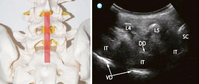
Fig.1 Left: midline position of the transducer (semitransparent red rectangle). Right: sonographic long-axis view of the lumbar spine showing the L4 (L4) and L5 (L5) spinous processes, the median S1 crest (SC), the hyperechoic lines of dorsal (DD) and ventral dura (VD), and the hypoechoic intrathecal (IT) space
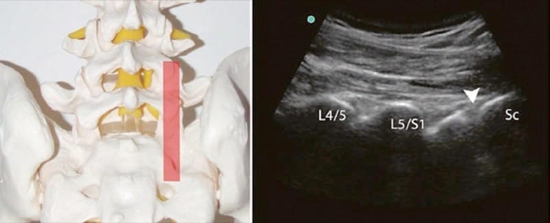
Fig.2 Left: paramedian position of the transducer (semitransparent red rectangle). Right: sonographic long-axis view of the lumbar spine with the L4/L5 (L4/L5) and L5/S1 (L5/S1) zygapophysial joint contours and the S1 (arrowhead) dorsal foramen. The joint gap is not visible in this view
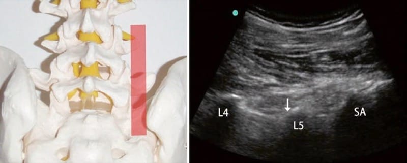
Fig.3 Left: lateral position of the transducer (semitransparent red rectangle). Right: sonographic long-axis view showing the L4 (L4) and L5 (L5) transverse processes and the sacral ala (SA). Upper edge of the transverse process, or the sacral ala, immediately lateral to the supe-rior articular process (arrow) is the correct anatomical target
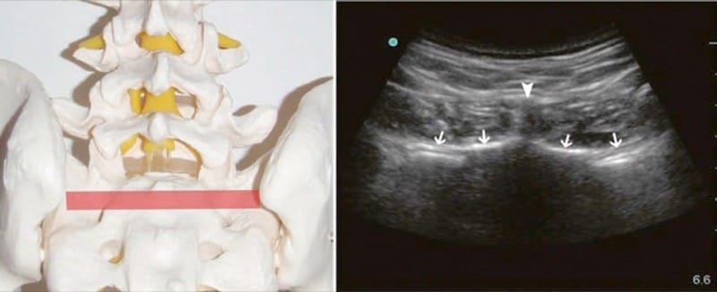
Fig.4 Left: axial position of the transducer (semitransparent red rectangle). Right: sonographic short-axis view of the sacrum showing the S1 median crest (arrowhead) and the hyperechoic surface (arrows) of the sacrum
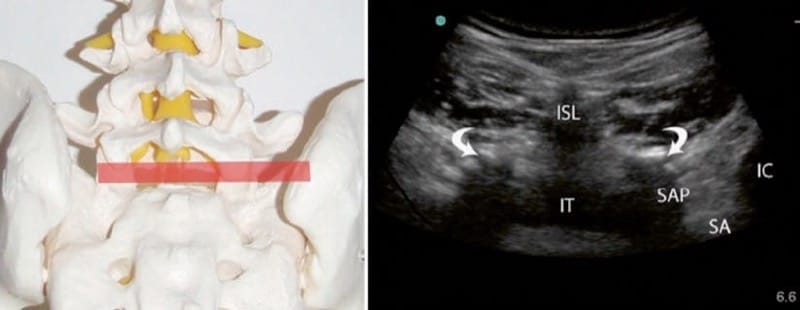
Fig.5 Left: axial position of the transducer (semitransparent red rectangle). Right: sonographic short-axis view of the lumbosacral seg-ment showing the hypoechoic L5/S1 interspinous ligament (ISL), the L5/S1 zygapophysial joints (curved arrows), the intrathecal (IT) space, the S1 superior articular process (SAP), the sacral ala (SA), and the iliac crest (IC)
Next midline hyperechoic signal, cephalad to the intrathecal space, is the L5 spinous process. At any lumbar level, two axial views can be obtained: the “interlaminar window” (Fig. 5) and the “spinous process/lamina window” (Fig. 6). (Note: At the “spinous process/lamina” position, the facet joint cannot be seen. Instead the exiting ventral ramus is occasionally visible.) It is advisable to continue cephalad scanning and identify all lumbar spinous processes and correlate those with the previously performed skin marking. This correlation will prevent injections at an erroneous level. When the transducer is firmly positioned at the desired level, a three-step shadow of the lumbar vertebra will become evident: the most superficial hyperechoic structure is the interspinous ligament or the spinous process, with the zygapophysial joint positioned just inferiorly and lateral to it and the transverse process located further inferiorly and laterally (Fig. 7). Fine tuning of the probe will help to “open the joint” and to visualize the angle between the superior articular and transverse processes. The latter is the anatomical target for the medial branch block (L1–L4). At the L5/S1 level, junction of the S1 SAP with the sacral ala should be targeted. Iliac crest is typically seen laterally to the sacral ala (Fig. 8).
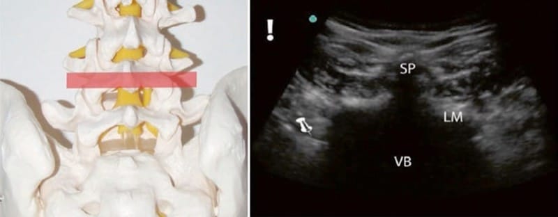
Fig.6 Left: axial position of the transducer (semitransparent red rectangle). Right: sonographic short-axis view of the L4 vertebra (bone window). L4 (SP) spinous process and L4 lamina (LM) are completely shadowing the L4 vertebral body (VB). Intrathecal space and the trans-verse process are not visible at this view. Exiting L4 nerve root is seen on the left (pin arrow)
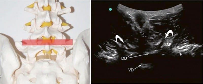
Fig.7 Left: axial position of the transducer (semitransparent red rectangle). Right: sonographic short-axis view of the L4/L5 segment showing the hypoechoic L4/L5 interspinous ligament (ISL), the L4/L5 zygapophysial joints (curved arrows), the dorsal (DD) and ventral dura (VD), the L5 SAP, and the L4 transverse process (TP)

Fig.8 Left: axial position of the transducer (semitransparent red rectangle). Right: sonographic short-axis right-sided view of the lum-bosacral segment showing the hypoechoic L5/S1 interspinous ligament (ISL), the ligamentum flavum (LF), the dorsal (DD) and ventral dura (VD), the intrathecal (IT) space, the right S1 superior articular process (SAP), the sacral ala (SA), and the iliac crest (IC)
4. INJECTION TECHNIQUE
Lumbar (L1–L4) Zygapophysial Medial Branch and L5 Dorsal Ramus Nerve Block
An antiseptic is utilized to prepare the skin at the block area. The US transducer is covered by a sterile sleeve. The patient is positioned prone with a pillow under the abdomen to diminish the lumbar lordosis. Sterile ultrasound gel should be used. The procedure begins with longitudinal scanning of the midline, starting from the sacrum as described above. The transducer is then rotated to obtain the short-axis view of the desired level. The previously described three-step shadow of the lumbar vertebra is obtained. Depth is measured and the insertion angle is estimated (Fig. 9). A block needle is inserted immediately next to the lateral edge of the transducer and advanced inplane until it contacts the bony surface at the root of the corresponding SAP (Fig. 10). The L5 dorsal ramus block can be technically challenging due to high iliac crest. If the iliac crest is obscuring the view, the injection may be done using an out-of-plane approach (see below). Alternatively, an oblique technique described by Greher at al. can be utilized. Once the bone contact is made, the transducer is rotated sagittally to obtain the longitudinal view and positioned paravertebrally at the “transverse processes” plane. The shadows of the transverse processes and/or the sacral alashould be localized. Agitation of the needle will help to identify its position in this out-of-plane sonographic view. The needle tip must be seen at the upper part of the transverse process or the sacral ala (Fig. 11). If the needle did not contact the bone at the predetermined depth, the longitudinal view should clarify the needle tip position relative to the transverse process. In this case, the needle tip will be seen somewhat below or above the bone shadow. Failure to recognize the tip position may result in transforaminal advancement of the needle and injury of the exiting nerve root.
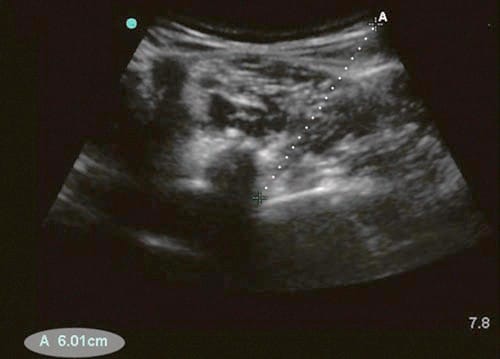
Fig.9 Short-axis view of a lumbar vertebra: lateral to the midline transducer positioning which improves visualization of the target and decreases injection angle. The skin to target distance (dotted line) is 6 cm
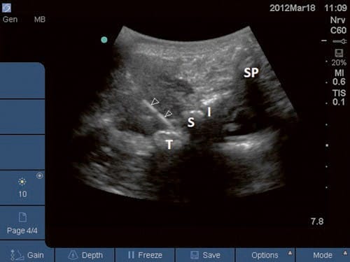
Fig.10 The needle (N) is positioned using the short-axis inplane approach to the angle between transverse (TP) and superior articular processes (SAP)
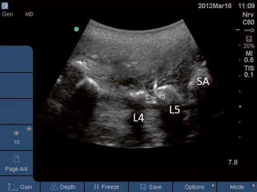
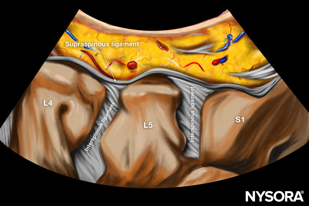
Fig.11 Final checkup of the needle (N) tip positioning at the upper part of the L5 transverse process (L5) is done utilizing long-axis out-of-plane view
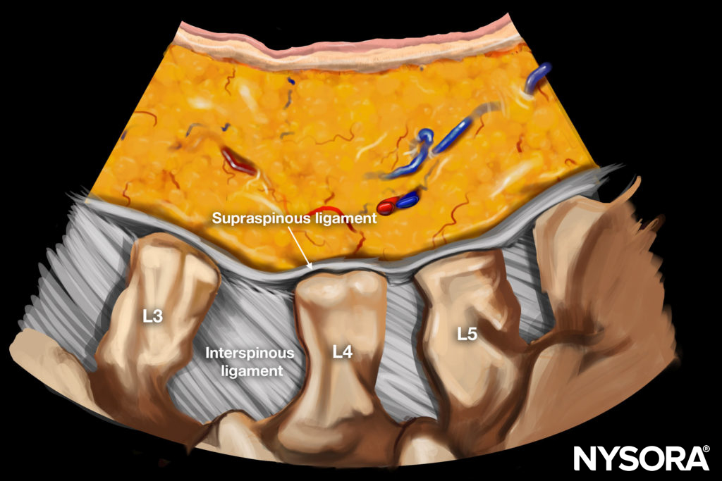
Reverse Ultrasound Anatomy illustration of figure 11.
After verification of the needle position, 0.5 ml of local anesthetic is injected. It is utmost important to visualize the tip during injection. High-resolution US allows observation of a hypoechoic expansion produced by the injectate. Failure to identify this phenomenon indicates an improper needle placement or intravascular injection. When the L5 dorsal ramus block is performed in an out-of-plane approach, the transducer is positioned at the level L5/S1 at the short axis. The root of the S1 SAP (the angle between S1 SAP and the sacral ala) is kept in the middle of image. The block needle is inserted immediately caudad to the midpoint of the transducer and advanced in the caudocephalad direction until the tip contacts the target, S1/sacral ala junction (Fig. 8). The longitudinal view should be applied to verify that the tip is not positioned beyond the sacral ala into the L5/S1 intervertebral foramen.
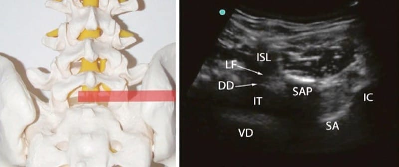
Fig.8 Left: axial position of the transducer (semitransparent red rectangle). Right: sonographic short-axis right-sided view of the lumbosacral segment showing the hypoechoic L5/S1 interspinous ligament (ISL), the ligamentum flavum (LF), the dorsal (DD) and ventral dura (VD), the intrathecal (IT) space, the right S1 superior articular process (SAP), the sacral ala (SA), and the iliac crest (IC)
5. INTRAARTICULAR LUMBAR ZYGAPOPHYSEAL JOINT INJECTION
The preparation and initial scanning are following the same protocol as for the medial branch injection. The transducer is held at the short-axis view to the corresponding lumbar vertebra, and a fine-tuning is performed to achieve the best sonogram of the posterior joint opening (the gap) (Fig. 12). A block needle is then inserted inplaneaiming the “gap”. It is unnecessary to force the needle between the superior and inferior articular processes. An accurate placement right at the posterior joint gap will assure a subcapsular location of the needle tip. Once the injection is initiated, a distinctive “bouncing” feeling will be appreciated, and an anechoic signal of the injected medicine should be traced next to the dorsal surface of the articular processes and into the joint. If the injection pressure is low and the injectate spread is registered into the multifidi muscles, the needle is placed outside the joint capsule.
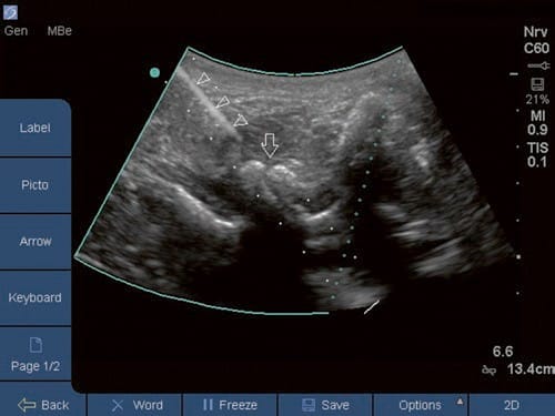
Fig.12 Lumbar facet joint injection. The needle (arrowheads) is directed toward the joint (arrow)
6. LIMITATIONS OF ULTRASOUND-GUIDED ZYGAPOPHYSIAL NERVE AND JOINT INJECTION
US guidance provides a feasible alternative to radiologic image-guided lumbar zygapophysial (facet) nerve and joint interventions. However, US guidance may not provide clear image acquisition in patients whose anatomic features pose particular challenges (e.g., obesity, severe degenerative changes, malformations). In addition, US cannot clearly detect an intravascular injection or inadvertent foraminal spread. Lastly, one of the largest limiting factors is the level of expertise and training of the sonographer.
Clinical updates
- Suputtitada et al. (Biomedicines, 2023) conducted a randomized study in 60 elderly patients with lumbar facet joint syndrome comparing ultrasound-guided medial branch block (0.25 mL D5W), intra-articular facet injection (up to 2 mL D5W), and multifidus muscle injection (5 mL D5W), showing all three techniques reduced median VAS from ~7–8 to ~1 after three biweekly injections, with no significant between-group differences. At 3 months, pain recurred partially (VAS ~4–5) but remained significantly improved from baseline (p<0.05), and the authors conclude that multifidus injection offers comparable analgesia with easier technical performance and fewer anatomical constraints than MBB or intra-articular injection.
Suputtitada A, Chen JL, Wu CK, Peng YN, Yen TY, Chen CPC. Determining the Most Suitable Ultrasound-Guided Injection Technique in Treating Lumbar Facet Joint Syndrome. Biomedicines. 2023;11(12):3308.