 Nerve Blocks App
 Pain Medicine Assistant App
 POCUS App
 IV Access App
 MSK Knee App
 VetRA App
 Nerve Block Manual
 Regional Anesthesia Updates
 Anesthesiology Manual
 Anesthesiology Review
 Anesthesia Updates 2025
 Anesthesia Updates 2026
 Pediatric Anesthesia Updates
 Airway Management Updates
 US Interventional Pain Manual
 Pain Medicine Updates
 Mastering Difficult IV Access
 PACU Nursing Manual
 RA Veterinary Manual
 About
About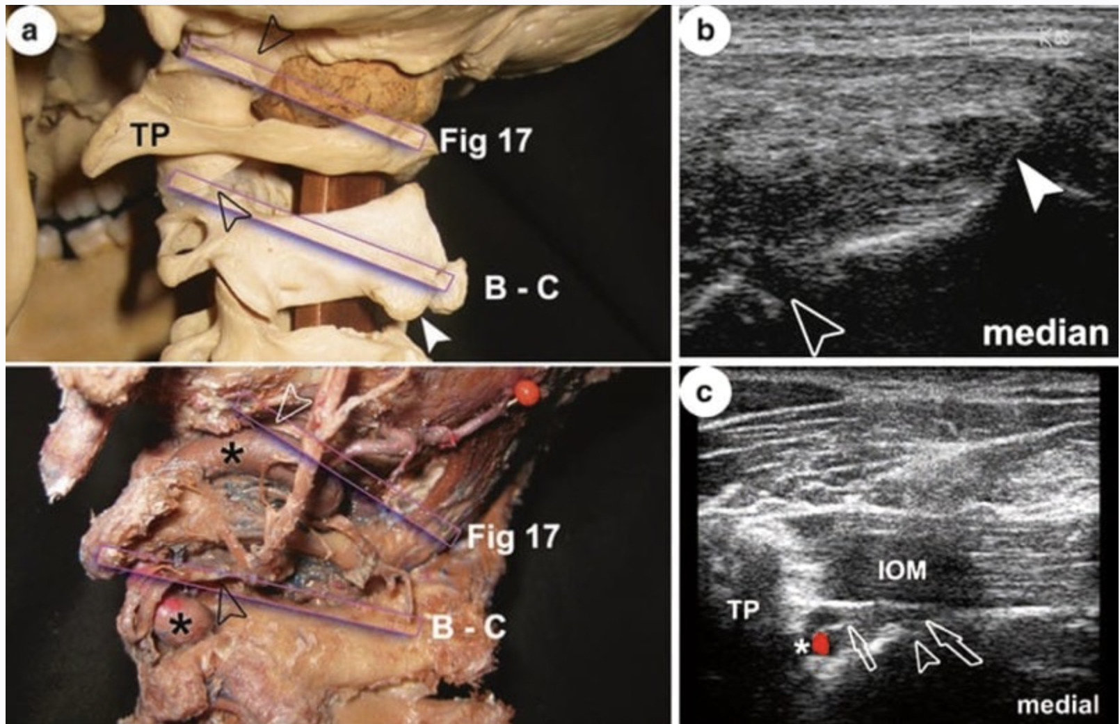
First and foremost, recognition of limits in performing ultrasound (US) imaging of the spine, associated spaces and joints is imperative before feasibilities may be fully appreciated. It is thus not surprising that some of the descriptions on approaches within parts of the spine (and pelvis) by means of sonography were published that can simply not withstand critical analysis. In addition, more than elsewhere in applying US in pain medicine, one has to be familiar with the usage of the right transducer (frequency) in the right area at individual patients and different settings. That way, all available transducers, technologies and possible frequencies play a practical role in proper spine imaging! Finally, the influence of positioning, movements and alterations of the spine (and thus age!) is tremendous and may either be challenging or make manoeuvres impossible. Accordingly, this chapter will first include a briefing on relevant anatomical peculiarities and variability of the spine from the skull to the coccyx, which is absolutely basic to understand the possibilities/limits in performing blocks and injections, respectively. Throughout the second part on relevant US images, emphasis will be laid on the differentiation between “superficial”, meaning bony contours (mainly posterolateral) or synovial joint capsules/entrances, and “deep”, which means articular cavities of the zygapophysial joints (ZJ) and sacroiliac joints (SIJ), vertebral canal, epidural space (EDS), paravertebral space, intervertebral foramina and nerve roots, sacral foramina and vertebral artery. As a rule, deep structures or spaces in the above-mentioned sense may only be reliably visualised ultrasonographically if “acoustic windows” are present (or created!) and used properly. That way and generally speaking, there is no US access to vertebral bodies or intervertebral discs and intervertebral foramina (thus nerve roots) of the thoracic spine (TS) and sacrum (S). Addressed structures are partly accessible in the lumbar spine (LS), but reliable visualisation is closely associated with BMI and/or individually highly different tissue properties that markedly influence echogenicity. So, with the important exception of the cervical part, direct visualisation of the sympathetic trunk is impossible. In the cervical spine (CS), a wider approach to the anterior aspect – including discs – is possible but partly limited by both airways and mandible. Despite the named difficulties, it will be shown that spine imaging using US, spine sonoanatomy, is as challenging as it is fascinating if one is familiar with and aware of intrinsic limitations!
1. CERVICAL SPINE
While all transverse processes (TP) of cervical vertebrae, C1–C7, possess foramina transversaria – hosting the vertebral artery (VA) and sympathetic plexuses from C6 upwards – only C3–C6 constantly show an anterior (usually the bigger) and posterior tubercle with the groove for the spinal nerve between them. Regularly, the posterior tubercles C3 through C5 are situated lower and lateral to the anterior ones. In clear contrast to the rest of the spine, the TP lie beside the vertebral bodies and are slightly directed downwards and anteriorly (Figs. 1 and 2).
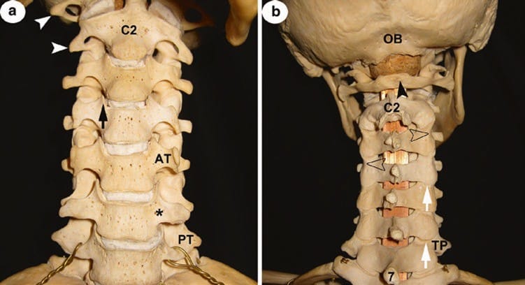
Fig. 1 (a) CS anterior view. C2 axis; white arrowheads pointing at transverse processes of atlas and axis with their foramina transversaria; black asterisk indicates groove at the base of transverse process C6; AT left anterior tubercle of C5. Note: in this individual, the C5 AT is bigger than that of C6, especially the right one! C7 has only a posterior tubercle, PT; from C5 to C3, all PT are lateral and lower to the AT; black arrow points at the uncinate process; (b) CS posterior view. OB occipital bone; seven spinous process, SP, of vertebra prominens; C2 axis with the bifid tip of SP; black arrowhead points at the rudimentary posterior tubercle of the atlas’ slim posterior arch. Open arrowheads point at the waist of articular pillars and white arrows at the posterior entrance into the cervical zygapophysial joints. Note the asymmetry of the length of TP in segments C2–C6!
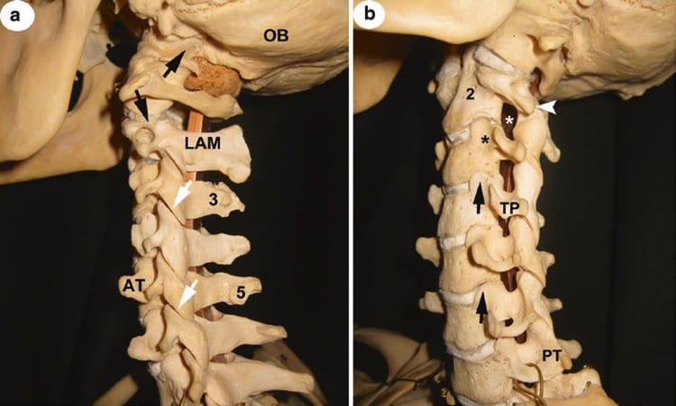
Fig. 2 (a) CS lateral view. OB occipital bone; LAM lamina of axis; three and five asymmetries of tubercles at spinous processes; AT anterior tubercle C5 of considerable size; white arrows point at the cervical zygapophysial joints; black ones indicate joint gaps of atlanto-occipital and atlanto-axial joints, respectively. Note their different orientations and widths of gaps. (b) CS anterolateral view. PT posterior tubercle of C7; TP transverse process C4; black arrows point at the uncinate processes; black asterisk indicates groove at the base of transverse process C3, white one in intervertebral foramen C2/C3. Two bodies of axis; white arrowhead on rudimentary TP of axis; note that foramina are only fully appreciated when CS is viewed from anterolateral and slightly inferior (the ones of C5/C6 and C6/C7 are therefore incompletely seen); compare with the view in (a)!
As TP are crucial landmarks for orientation, it is important to add that:
- Apart from the atlas (C1) and C7, all other TP are relatively short (Fig. 1b).
- The TP of C1 project more laterally than all others (Fig. 1b).
- The TP of C2 are often rudimentary as an anterior tubercle is not clearly developed (Figs. 1a and 2a, b).
- The anterior tubercle of TP C6, usually referred to as the biggest (“carotid tubercle”, tubercle of Chassaignac), may vary considerably in size (!), even between both sides of the same individual (Fig. 1a).
- The TP of C7 has no anterior tubercle (Figs. 1a, 2a, b); all TP may vary according to size and length.
Another noteworthy and constant morphological feature true for C3–C6(7) is the marked but unnamed groove at the base of TP. Above this groove, the upper surfaces of corpses C3–C7 raise liplike to form the uncinate processes. They reach as far cranial as the lower contour of the next body; so they completely cover (and protect) the whole lateral aspect of the intervertebral disc (Figs. 1 and 2b).
Cervical ribs (Fig. 3) of various lengths and massiveness may occur if the rib anlagen of the TP remain independent, most commonly seen bilateral (more frequent on the left side if unilateral). Such an entity should be thought of if sensory disturbances occur related to the brachial plexus.
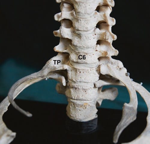
Fig. 3 Bilateral cervical ribs (with ligamentous extensions). The smaller with ankylosis to transverse process, TP, of C7. Note the asymmetry of transverse processes from C6 upwards, especially comparing anterior tubercles
Intervertebral foramina, the largest of which is between C2 and C3, are not seen in lateral views (Fig. 2a, b).
In contrast to C7, the tips of spinous processes (SP) appear bifurcated in most individuals but very often asymmetrical, unequal in size, and not infrequently poorly developed or just indicated at C5 and C6. Moreover, SP often deviate either to the right or the left (Fig. 1b).
The cervical zygapophysial joints (CZJ), also named “facet joints”, are plain joints with their inferior articular surfaces facing forwards and downwards, in conformity with the superior ones facing backwards and upwards. In general, the narrow joint gaps are best appreciated in a lateral view! Only that between C2 and C3 differs as the two surfaces of C3 are at an angle of 142° to each other (Figs. 1b, 2a, and 4a, b). Viewed from posterior, superior, and inferior, articular processes (AP) of each vertebra (“articular pillars”) with their marked waist between them create a wavy appearance of the lateral borders of the CS from C2 to C7 (Fig. 1b).

Fig. 4 (a) Atlanto-occipital (AO), atlanto-axial (AA) and cervical zygapophysial joints (CZJ), posterior view. Posterior arch of atlas, SP and LAM C2–C5 as well as the occipital bone removed. D dura mater; black arrows indicate AOJ, AAJ and CZJ of C3/C4 and C2/C3! White arrowheads show ventral rami of spinal cervical nerves; open arrowheads show second dorsal root ganglia. Note the course of the vertebral artery (black asterisks) relative to AOJ and AAJ as well as to the nerve roots. (b) Posterolateral view of specimen in (a). Symbols for labelling as in (a). Note the width of AAJ gap.
Due to the lack of both vertebral body and SP, the atlas is unique among vertebrae. It has two arches, anterior and posterior. The latter is usually very slim, its height approximately only half the size of a regular lamina (LAM) and its “median” posterior tubercle often rudimentary or absent. As a result, the atlanto-occipital and atlanto-axial gaps (acoustic windows) are considerably wider compared to those between LAM and SP of C2–C7 (Figs. 1b and 2a). The distance from the skin to the posterior arch differs significantly, not least influenced by the individual shape of the neurocranium.
Finally, the atlanto-occipital joint (AOJ) and atlanto-axial joint (AAJ), “upperhead” and “lowerhead joints”, are also unique among CS diarthroses: the former is an ellipsoid joint and the latter part of a (functionally) rotary one with a considerable wide joint gap. Importantly, the AAJ is bordered by the C2 dorsal root ganglion (DRG; dorsomedial) and the vertebral artery (VA; lateral); consecutively the VA regularly runs inferior and medial to the AOJ (Figs. 2a and 4a, b). In case of elongation, the VA may also cross both joints dorsally!
In summary, all mentioned features of CS anatomy should remind US users that there is (a) no symmetry within one individual and (b) practically relevant interindividual variability (Sir William Osler: “… and as no to faces are the same, so no two bodies are alike …”). Special attention has to be paid to atlas and axis with their respective joints!
2. THORACIC SPINE
The second through the tenth thoracic vertebrae, T2–T10, may be viewed as “typical”. In contrast to the situation at the CS, the sturdy transverse processes (TP) lie lateral and a little posterior to the articular processes and are directed upwards (except T10) and posteriorly. They articulate with the tubercles of their respective ribs, the neck of which lies anterior (thus hidden) to the transverse processes until T4. From there to T9, the ribs’ neck progressively projects the TP (Fig. 5a), important for paravertebral blocks (narrow acoustic windows). There is little variability as far as the size and length of these TP. In contrast, TP of T11 and T12 are often rudimentary and, as occurs in the LS, show accessory and mammillary processes in various degrees and shapes. In addition, T12 often develops an indicated (rudimentary) costal process (CP) (Fig. 5b).
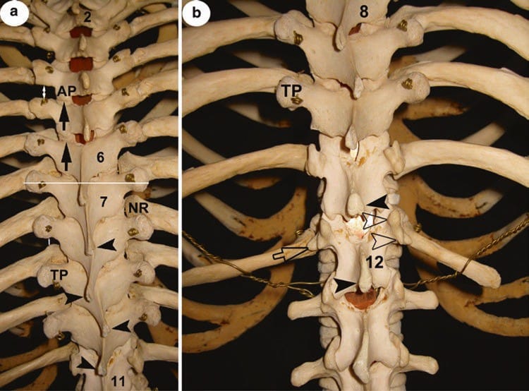
Fig..5 (a) Posterior view of TS from T2 to T11. 2, 6, 7 and 11 lamina of respective thoracic vertebra; AP inferior articular process of T4; black arrows point at the posterior entrance into the thoracic zygapophysial joints. Note the differences in the upper and lower part of TS. TP transverse process of T9; NR neck of eighth rib; white double arrows indicate examples of different “acoustic windows” in different thoracic levels; black arrowheads indicate tips of spinous processes, SP, T8– T11; the white line through both TP of T7 hits the SP of T6! (b) 8, 12 lamina, LAM, of respective thoracic vertebra; TP transverse process of T10; TP of T11 and T12 are rudimentary but clearly show mammillary and accessory processes (open arrowheads); open arrow points at an equivalent of a lumbar costal process in T12! Black arrowheads indicate tips of SP T11 and T12. Note the width between LAM and SP at T11/T12 level compared to segments above! (See text for more details)
The spinous processes (SP) of the second through ninth thoracic vertebrae are arranged like roof tiles. This is most accentuated from T5 to T9, creating an osseous barrier (no acoustic window!). As a consequence, a transverse section through both TP of a given vertebra will show the SP of the next higher segment (Fig. 5a)! Quite similar to the situation in the CS, the SP of a (perfectly regular) TS often deviate, meaning their tips are paramedian, sometimes even by turns of each segment in certain parts (Fig. 5a, b). The orientation of the SP of T10 varies; most commonly it only slightly descends, while those of T11 and 12 extend directly dorsally, giving space (allowing better access) between them (Fig. 5b).
A typical feature of T1–T10 is the width of their lamina (LAM) which exceeds over that of their bodies (Fig. 6a). Together with the SP, both LAM of a single vertebra form a bow. Not so with T11 and T12 (due to their similarity with lumbar vertebrae; see also below), because their LAM is sturdy and narrow, essentially facing posteriorly (Fig. 5b). The thoracic zygapophysial joints (TZJ) are plain joints as those in the CS (with similar narrow cavity), but the position of the joint surfaces represents segments of a cylinder (except the one between T11 and T12): they face backwards and slightly outwards at the superior and forwards and inwards at the inferior AP. As in the CS, the inferior AP almost completely covers the superior AP of the next vertebrae (not so at T12/L1). This arrangement impedes access to most of the joint entrances in contrast to the more exposed costotransverse joints (Fig. 6b). Synovial capsules of all costotransverse articulations are surrounded by a rather strong ligamentous apparatus! There are no such joints at T11 and T12 (rudimentary transverse processes and lack of costal tubercles at ribs 11 and 12).
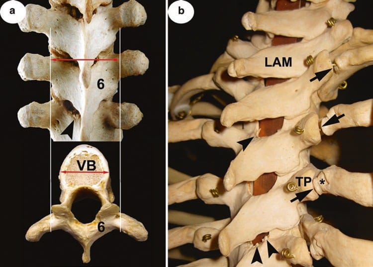
Fig. 6 (a) Posterior view of the middle part of TS with insert of a typical thoracic vertebra. Six lamina, LAM, of T6; double arrows compare the width of LAM with that of the body, VB; black arrowhead points at a typical bony spur from the upper margin of T7 LAM (partly ossification of yellow ligament!). (b) Posterolateral view of the upper thoracic spine. LAM lamina of T1; asterisk shows the tubercle of the fourth rib, TP transverse process of T4; black arrows indicate costotransverse diarthrose and black arrowheads beginning ossification of yellow ligaments. Note that windows between LAM are relatively wide in this part of TS (compare with Fig. 5a, b).
Due to the peculiarities of anatomy mentioned, the TS is a difficult part for US exploration, and one has to consider uppermost, lowermost, and middle parts differently.
3. LUMBAR SPINE
With the exception of the fifth lumbar vertebra, L1–L4 show similar features and are therefore representative. Their costal processes (CP) or “transverse processes” (TP) (see below) are regularly slim and long, pointing lateral in essence. The dorsal surface of CP faces strictly posterior. Apparently different to the TS, CP are situated anterior (!) to the AP. This is because they constitute the homologue of a rib (and therefore CP is the more accurate terminology). In case of non-fusion with the vertebra, a lumbar rib occurs in approximately 8% of individuals. Apart from this entity, there is a noteworthy variability concerning the length, width/height and “massiveness” of CP. This includes marked differences in different levels as well as on both sides of a single spine. Especially, a rudimentary (very short and slender) CP is of practical relevance, most frequently seen at L4 (Figs. 7 and 9b). Uninfluenced by such variability, at the root of each CP, a small but rough accessory process is present in most cases. Together with another protrusion, mammillary process, at the dorsal margin of the superior AP, they are remnants of true transverse processes, which are only seen in the TS (Figs. 5b, 7 and 8b). Very often both are distinguishable by means of sonography. One of the outstanding signs of L5 is the massiveness of its CP (Figs. 8a and 9b). Moreover, its dorsal surface looks slightly upwards.
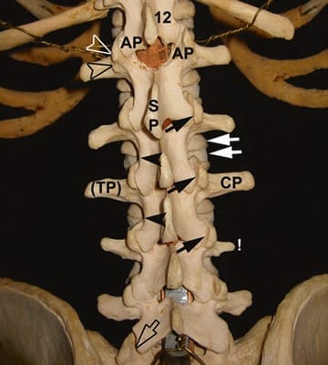
Fig. 7 Posterior view of LS. Twelve lamina, LAM, of T12; AP facing articular processes of T12 (inferior AP) and L1 (superior AP); open arrowheads indicate mammillary process at superior AP and accessory processes at the root of costal process, CP (“transverse processes”, TP); SP spinous process of L1; black arrows point at the lumbar zygapophysial joints, LZJ; white ones indicate the vertebral body of L2 and intervertebral disc, respectively; black arrowheads at the waists of LAM L2 and L3. Note (!) rudimentary CP of L4 and different “shapes” of CP throughout LS. Open arrow points at the LSJ that differs from LZJ above.
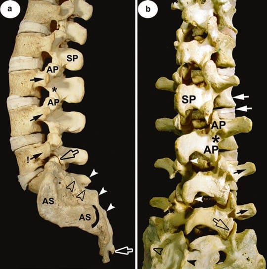
Fig. 8 (a) Lateral view of the LS and sacrum. SP spinous process of L2; AP superior and inferior articular process of L3 with “interarticular portion” (asterisk) in between; black arrows indicate costal processes L3–L5, the latter more massive than all others (!). Black open arrow points at joint gap of LSJ (those of LZJ not visible!). AS articular surface; arched line marks posterior end; the median sacral crest (white arrowheads) and lateral sacral crest (open arrowheads) are labelled; white open arrow points to (left) the sacral horn. Note the huge distance and area between lateral sacral crest and AS, the sacral tuberosity! (b) Posterolateral view of the LS (and sacrum). Interspinous and interlaminar spaces widened by abolition of lordosis compared to (a). White arrowheads indicate caudal extension of SP and white arrows vertebral body of L2 and intervertebral disc, respectively; open arrowhead indicate lateral sacral crest and black arrowhead median sacral crest. L3 and L5 with particularly prominent accessory processes at the root of CP (compare with Fig. 7). Note the shape and orientation of lamina L5, considerably different from others! Sacrum: note incomplete fusion at the upper part of the median sacral crest.
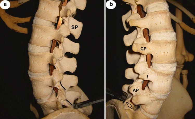
Fig. 9 (a) Lateral view of LS. SP spinous process of L1; compare with Fig. 8a (similar grade of lordosis) for interindividual differences, especially concerning the shape, massiveness, etc., as well as orientation of SP L1–L5. They are responsible for different interspinous space. Note the orientation of laminae (outlined) of L4 and L5. (b) Anterolateral view of LS (L2–L5). AP superior articular process of L5; CP costal process L3; compare with (a) and Fig. 7 (same individual) for side differences, especially concerning the shape, massiveness and orientation of CP L2–L5. Open arrow points at articular surface of inferior AP of L5 (orientation!).
The spinous processes are massive (L5 the least substantial in contrast to its CP), rectangular and sagittally orientated. Their upper margin is approximately in line with the lower margins of both CP; the lower margin reaches at least to the level of the intervertebral disc (in projection). The dorsal border is thickened, often revealing an extension at its caudal end (Figs. 8a, b and 9b).
Opposed to the TS, the width of the high but sturdy L1– L4 laminae (LAM) is much less than that of their bodies. Therefore, a considerable part of vertebral bodies and dorsal aspects of intervertebral discs are seen in a dorsal view. Showing a clear waist, all LAM are narrowest between superior and inferior AP, at the so-called interarticular part (Fig. 7). At the same time, this waist indicates the level and position of the lumbar dorsal root ganglia, DRG. The LAM faces posteriorly from L1 to L3 and posteriorly and slightly upwards in L4, while the extensively broad but low L5 LAM looks more upwards than posterior (Figs. 8b and 9a).
The articular facets of the lumbar zygapophysial joints (LZJ) are principally convex (at the inferior AP) and concave (at the superior AP), in essence facing laterally and medially, respectively. This is why joint gaps are best seen in a posterior view (Fig. 7). However, the position of the facets is highly variable, not infrequently asymmetrical and showing angulations. Restriction of movements is realized by a very strong ligamentous apparatus, especially by transversely orientated dorsal capsular ligaments (Fig. 10). At the lumbosacral joint (LSJ), the“ZJ” between the inferior AP of L5 and superior AP of sacrum, variability concerning facets, is even higher (asymmetry in 60%!), but joint surfaces at the inferior AP of L5 look principally anterolateral (Figs. 7, 8a, b, and 9b). The articulation is additionally protected from overloading by the strong iliolumbar ligament.
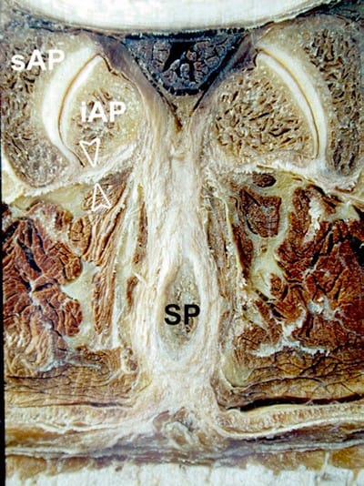
Fig.10 Transverse section through lumbar zygapophysial joint, LZJ, between L3 and L4. SP and iAP spinous process and inferior articular process of L3; sAP superior articular process of L4. Note the hooked shape of LZJ on the left side compared to the right as well as thickness of capsular ligament (open arrowheads)!
LS anatomy reveals that this part of the spine is more “open” to US examination as compared to the thoracic part, not least by augmentation of acoustic windows through motion. However, structures of interest lie deeper, and in addition, a solid knowledge of variability is crucial.
4. SACRUM
The curved sacrum is formed by the fusion of five sacral vertebrae with their respective intervertebral discs and ligaments. It explains why after fusion is completed, we no longer see lateral processes (neither TP nor CP) but what is called lateral part at the pelvic surface and lateral sacral crest at the convex dorsal surface (Figs. 11a, b), which is obviously more important for US. While the aforementioned crest, representing remnants of the transverse processes, is always clearly seen (and thus a good landmark in US images), the intermediate sacral crest is often poorly developed (representing union of articular processes). The median sacral crest is formed by the fusion of the spinous processes (SP) of S1–S4, thus the most prominent of all longitudinal ridges. Not infrequently, this fusion includes only three SP or is incomplete throughout the midline (Fig.12a, b)! Incomplete fusion is seen in 10% of adults aged 50, in which cases the sacral canal appears partly opened (comparable to the vertebral canal at the LS)! Regularly, however, both laminae of the fifth sacral segment fail to fuse in the midline to leave the sacral hiatus that leads into the sacral canal. The height and shape of the hiatus depend on the number and mode of fused SP (see above!) but are in its caudal part always laterally bordered by the sacral cornu, the most important of all palpable landmarks (Fig. 11a). Interestingly, complete synostosis of all sacral parts and elements happens as late as 25–35 years of age, in some individuals never, which explains all forms of variants so frequently encountered and thus practically important (Figs. 11a and 12b).
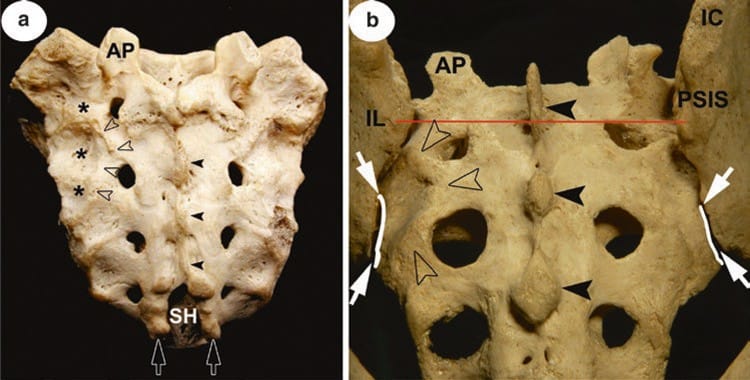
Fig.11 (a) Isolated sacrum, dorsal surface. AP superior articular process; SH sacral hiatus; open arrowheads indicate lateral sacral crest and black arrowheads median sacral crest; white open arrows point at sacral horns; asterisks mark the sacral tuberosity. Note the relatively small posterior sacral foramina in this specimen as compared to (b). Sacrum in situ, dorsal view. IL ilium with iliac crest, IC, and posterior superior iliac spine, PSIS; white arrows delineate entrance into the posteriormost (directly accessible) part of the sacroiliac joint cavity, SIJ; curved lines mark the posterior rim of sacral articular surfaces. Note that the gap seen above does not lead to or correspond with SIJ! The transverse line through both PSIS indicates the level of cross-section in Fig. 13a.
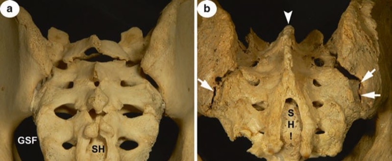
Fig. 12 (a) Sacrum in situ, dorsal view. SH sacral hiatus; GSF greater sciatic foramen. Note the incomplete ossification with partly open sacral canal and non-fusion of S1 segment. (b) Sacrum in situ, dorsal view. Note the prominent but shortened median sacral crest (white arrowhead) due to non-fusion of laminae of S4 that results in an extraordinary high SH! Entrance into SIJ (white arrows) partly obscured by ossification. Compare both (a) and (b) with Fig.11a, b!
Concerning the above-mentioned variability, the posterior or dorsal sacral foramina differ from small to huge as well as their number (Figs. 11a, b and 12a). The latter occurs as frequent as in one-third of the population, either due to sacralization of a lumbar vertebra or a coccygeal element (both with five foramina on either side). This is seen more often in males. Sacral foramina, anterior or posterior, should not be misinterpreted as equivalents to the intervertebral foramina of the rest of the spine! In the sacrum, they lie within the sacral canal as lateral openings.
It is of utmost importance to realize that a considerable area of the dorsal surface of the sacrum, roughly corresponding to the sacral tuberosity, is overlaid by the wing of the ilium. As the tuberosity lies mainly above the auricular surface, most of the SIJ cavity is also completely and deeply hidden (Fig. 13a, b). As a consequence, only the most posterior part of the joint cavity (gap) is visible from the posterior (Fig.11b), and this is important for US approach.
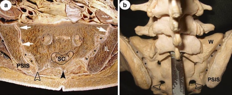
Fig.13 (a) Cross-section through the pelvis at the level of PSIS. SC sacral canal; black arrowhead points at median sacral crest, open one at (very prominent) lateral sacral crest. Note that at this level the joint cavity of the sacroiliac articulation (white arrows) is in far distance from the dorsal body surface. The space from joint cavity to lateral sacral crest is filled with interosseous ligaments (asterisks) attached to facing iliac and sacral tuberosities. The latter is almost completely covered by the wing of ilium, IL! Compare with (b). Sacrum in situ viewed from above. PSIS posterior superior iliac spine; W wing of sacrum; open arrows point at lateral sacral crests; a mass (asterisks) simulates interosseous ligaments
Although most of the dorsal surface of the sacrum is easily accessible by US, the anatomy of the sacrum is tremendously influenced by its most variable progress of ossification (fusion) and non-ossification.
5. SONOANATOMY OF THE CERVICAL SPINE: SUPERFICIAL
While there is no chance to image atlas (C1) and axis (C2) ventrally, the posterior arch of C2 with its typical features mentioned in the anatomy part (see above) and articular pillar, lamina as well as the bifurcated (two tubercles) spinous process of C2 are easily seen and may serve as ideal landmarks. As for C2, the same is true down to C6 (Fig. 14a–c). In addition, the occipital bone is well appreciated with US with appropriate transducers, and thus atlanto-occipital and atlanto-axial windows are easily detectable (Fig. 15a, b). To give practical examples, these bony surfaces may be used as landmarks for approaching both AAJ and AOJ as well as the greater occipital nerve (GON) more centrally (Figs. 16a–c, 17a, b and 18a–c).
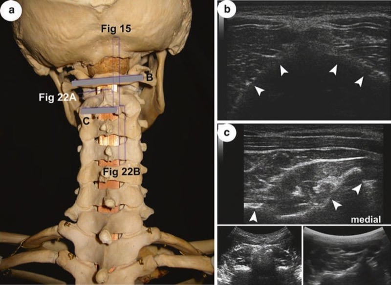
Fig. 14 (a) Scanning planes for US images (b) and (c) and for Fig. 15 relative to the skull and upper CS; posterior view. (b) Dorsal surface of posterior arch of atlas (arrowheads). Note that the quality of image is not least depending on highly variable degree of bone curvature! (c) Bony outlines of axis, C2. Arrowheads indicate from medial to lateral: bifid spinous process, SP, lamina and inferior articular process. To get a better overview of the vertebrae, usage of curvilinear probes is recommendable; see inserts at the bottom right (paramedian) and left (median position of transducer).
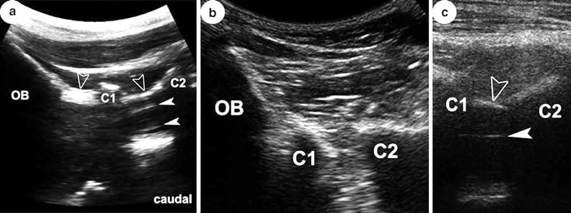
Fig. 15 (a) See Fig. 14a for scanning plane! All labelling also applies for (b) and (c). OB occipital bone; C1 posterior arch of atlas; C2 lamina of axis; open arrowheads point at the atlanto-occipital and atlanto-axial membrane, respectively; white arrowheads indicate dura mater. Note the narrow interosseous gaps in (b) due to retroflexion! (See text for more details)
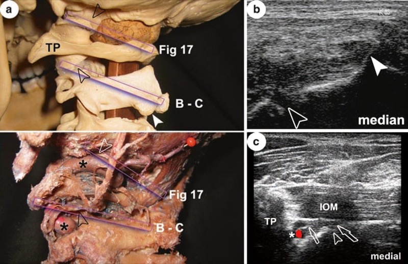
Fig. 16 (a) Scanning planes for US images (b) and (c) and for Fig. 17 relative to skeleton (upper) and special preparation (lower) of uppermost CS and skull base. Open arrowheads mark AAJ and AOJ; white arrowhead indicates left tubercle of C2 spinous process, SP; asterisks show vertebral artery, VA. Note that the VA shows elongation, so part of the AOJ is hidden; TP transverse process of atlas; all labelling also applies for (b) and (c). (b) Demonstration of AAJ gap. (c) IOM inferior oblique muscle. Note that this scan is more horizontal and reaches more lateral (no SP seen) compared to (b) to show the TP, VA as well as 2nd dorsal root ganglion and ventral ramus (open arrows).
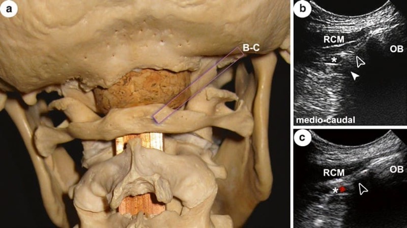
Fig. 17 (a) Scanning plane for US images (b) and (c) relative to the occipital bone (OB) and uppermost CS; see Fig.16a for comparison. (b) and (c) Different appearance of AOJ gap (open arrowhead); note the regular relation of vertebral artery (asterisk) infero-medial to joint; white arrowhead in (b) indicates bone shadow by lateral mass of atlas; RCM rectus capitis major muscle.
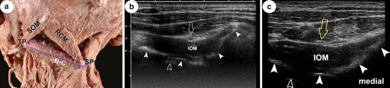
Fig. 18 (a) Scanning plane for US images (b) and (c) in an anatomic specimen of short muscles of the neck; open bar on inferior oblique muscle; SOM superior oblique muscle; RCM rectus capitis major muscle; OB occipital bone; TP transverse process of atlas; SP spinous process of axis; posterolateral view. (b) and (c) White arrowheads indicate from medial to lateral: SP, lamina and superior articular process of axis and lateral mass of atlas, respectively. The GON (open arrow) lies “on top” of IOM. Note that in both images, the AAJ (open arrowhead) is also seen.
The above-mentioned joints lie relatively deep compared to the CZJ and are bordered by the vertebral artery (VA). CZJ can be located either laterally or posteriorly, and capsular ligaments may be detectable where stronger. Lying directly on the bone, the third occipital nerve (TON) and “medial branches” C3 and C4 are visible (Fig. 19a–c). The outlines of transverse processes from C3 to C6 including anterior and posterior tubercles are accessible from lateral and thus most valuable landmarks, e.g. for nerve root location and general orientation (Figs. 20a–c and 24a).
Anterior longitudinal scans reveal the typical shape of vertebral bodies (and anterior aspects of discs in between) covered by the anterior longitudinal ligament; in transverse views, the anterior tubercles of TP C3–C6 and the marked groove at the base of each TP are appreciated. As C7 lacks an anterior tubercle, its TP appear completely different, and the VA has no bony covering at that segment (Fig. 21a–c; C6 and Figs. 23c and 24b).
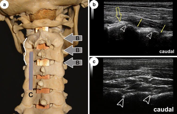
Fig. 19 (a) Scanning planes for US images (b) and (c) relative to CS; posterior view. Note the wavy lateral outline of CS by typical shape of articular pillars (white line). (b) Visibility of (entrance into) joint gaps (open arrowheads) depends on obliquity of lateral scan; arrows indicate medial branches C3 and C4; open arrowhead points to TON. This image was done with an 18 MHz probe! (c) Scan on dorsal surface of articular processes. Note that gaps are only indicated (compared to b) by “steps” (open arrowheads).
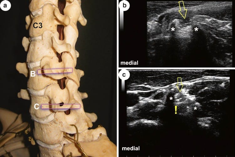
Fig. 20 (a) Scanning planes for US images (b) and (c) relative to CS; anterolateral view. (b) and (c) TP transverse processes of C5 and C6 (hit at their lateral end); asterisks mark anterior and posterior tubercles; open arrows point at ventral rami. Note the mirror artefact (!) in (c) that may be misinterpreted as the true nerve! See also Fig. 24 and text for more details
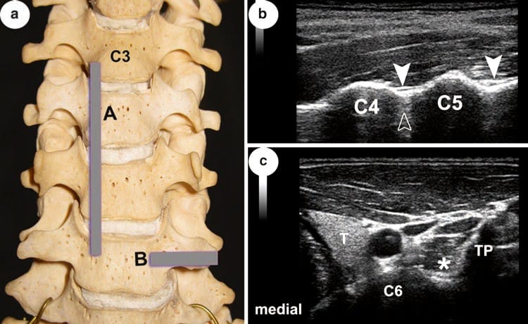
Fig. 21 (a) Scanning planes for US images (b) and (c) relative to CS; anterior view. (b) C4 and C5 vertebral bodies of respective vertebrae; arrowheads indicate anterior longitudinal ligament; open arrowhead indicates intervertebral disc. (c) TP transverse process; asterisk in longus colli muscle indicates groove at the base of TP; T thyroid gland. (See text for more details)
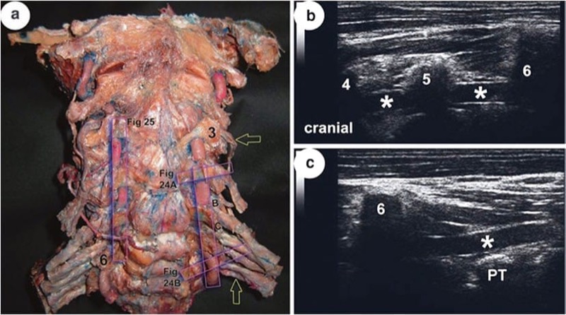
Fig. 23 (a) Scanning planes of US images (a) and (b) and for Figs. 24 and 25 in an anatomic preparation of CS with injected (red latex) vertebral artery, VA, and ventral rami of spinal nerves C3–T1 (open arrows); anterior view. Three and six anterior tubercles of transverse processes of respective vertebrae. (b) and (c) Lower cervical and prevertebral part of VA (asterisks); PT posterior tubercle of transverse process of seventh cervical vertebra. (See text for more details)

Fig. 24 See Fig. 23a for scanning planes. (a) and (b) C4 and C7 roots (open arrows) at transverse processes, TP. Note different appearance of TP of vertebra prominens relative to that of the fourth, its length and lack of an anterior tubercle (asterisk). This is why the VA (arrowhead) is freely accessible at that level in transverse views. Note the relation to nerve root and do not mix both with other “black balls” also seen (C5 and C6 roots, open arrowheads). (See text for more details)
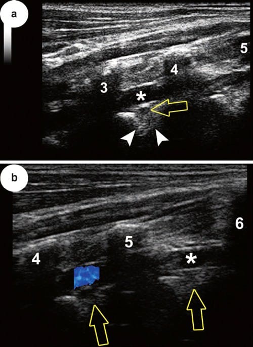
Fig. 25 See Fig. 23a for scanning plane (a) and (b) cervical part of VA (asterisks and blue colour) through and between transverse processes from third to sixth vertebra. Note that nerve roots lie dorsal to artery; in (a) outlines of the intervertebral foramen are seen too. (See text for more details)
6. SONOANATOMY OF THE CERVICAL SPINE: DEEP
Demonstrating EDS, dura mater (D) and spinal cord is done from posterior and preferably paramedian, the biggest acoustic window to be found between atlas and axis and atlas and occiput. With maximum anteflexion, however, the other interlaminar gaps allow sufficient access as well (Fig. 22a). The VA runs through the foramina transversaria, its “free” part, obviously limited, easily detectable with an anterior longitudinal approach (Fig. 23a–c). Although more challenging, showing the VA in relation to the AOJ and AAJ is also feasible in most cases. Ventral rami of spinal nerves can be traced at least until their position within the respective sulcus from C3 to C7 (Fig. 24a, b: US C3 and C7). Moreover, it is often possible to reliably demonstrate their relationship with the VA in mentioned segments; the nerves lie dorsal to it and can be followed right to their exit from the intervertebral foramina (Fig. 25a, b)! At least from C3/C4 downwards, anterior aspects of the intervertebral discs can be visualised. This is not possible for their anterolateral circumference due to the bony covering by the uncinate processes as mentioned above.
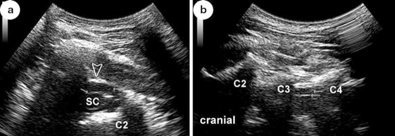
Fig. 22 (a) Transverse scan through atlanto-axial space into vertebral canal with spinal cord, SC; arrows point at dura and epidural space, EDS, respectively. The latter ends dorsally at the atlanto-axial membrane (open arrowhead); C2 bone shadows by body and superior articular process of atlas. (b) Demonstration of vertebral canal with SC in a paramedian longitudinal scan. C2 right tubercle of spinous process of axis; C3 and C4 laminae of respective vertebrae; arrows point – from superficial to deep – at yellow ligament (double contour!), EDS and dorsal surface of dural sac. See text for more details

Fig. 23 (a) Scanning planes of US images (a) and (b) and for Figs. 24 and 25 in an anatomic preparation of CS with injected (red latex) vertebral artery, VA, and ventral rami of spinal nerves C3–T1 (open arrows); anterior view. Three and six anterior tubercles of transverse processes of respective vertebrae. (b) and (c) Lower cervical and prevertebral part of VA (asterisks); PT posterior tubercle of transverse process of seventh cervical vertebra. (See text for more details)
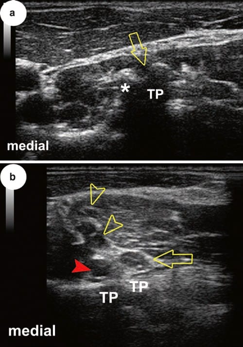
Fig. 24 See Fig. 23a for scanning planes. (a) and (b) C4 and C7 roots (open arrows) at transverse processes, TP. Note different appearance of TP of vertebra prominens relative to that of the fourth, its length and lack of an anterior tubercle (asterisk). This is why the VA (arrowhead) is freely accessible at that level in transverse views. Note the relation to nerve root and do not mix both with other “black balls” also seen (C5 and C6 roots, open arrowheads). (See text for more details)

Fig. 25 See Fig. 23a for scanning plane (a) and (b) cervical part of VA (asterisks and blue colour) through and between transverse processes from third to sixth vertebra. Note that nerve roots lie dorsal to artery; in (a) outlines of the intervertebral foramen are seen too. (See text for more details)
7. SONOANATOMY OF THE THORACIC SPINE: SUPERFICIAL
All of the dorsal surface of the thoracic vertebrae can be appreciated with US. Especially the contours of the transverse and articular processes together with the necks of ribs are ideal landmarks to find acoustic windows for entering the paravertebral space. The ribs within the “intertransverse window” are ultrasonographically seen in longitudinal scans from level T4 or T5 downwards as they project the transverse processes (Fig. 26a–c). Likewise, entrance into the costotransverse joints is often possible, and the lateral costotransverse ligament is clearly detectable; not so with the TZJ (Fig. 27a, b). Due to their small dimensions, TP of vertebra T11 and T12 may cause difficulties in identification and/or orientation in that lowermost part of the TS (Fig. 27c).
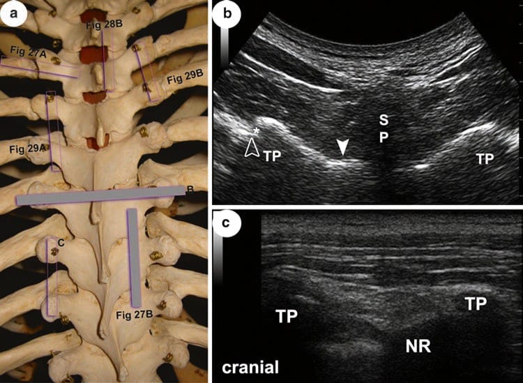
Fig. 26 (a) Scanning planes of US images (a) and (b) relative to TS; posterior view. (b) TP dorsal surface of transverse processes T7; SP shadow by spinous process of T6! White arrowhead on lamina of T7; open arrowhead marks tubercle of seventh rib. Note the gap between TP and tubercle (entrance into costo-vertebral joint; asterisk). (c) TP transverse processes of T8 and T9; NR neck of ninth rib. (See text for more details)
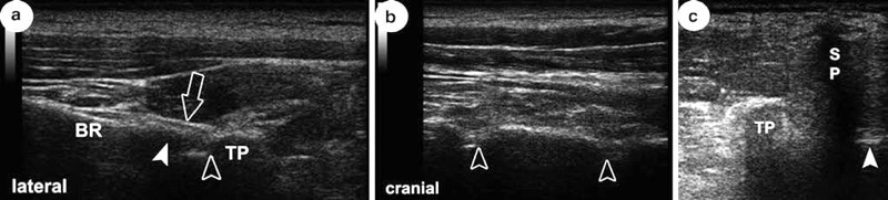
Fig. 27 See Fig. 26a for scanning planes in (a) and (b), Fig. 28a for plane of US image shown in (c). (a) TP transverse process of T4; BR body of rib; arrowhead marks tubercle of rib; open arrowhead points at costotransverse joint (gap); open arrow indicates lateral costotransverse ligament. (a) Scan on dorsal surface of articular processes. Note that gaps are only indicated (compared to b) by “steps” (open arrowheads). (c) TP rudimentary transverse process of T11; SP bone shadow by spinous process of T10; arrowhead points at right lamina. (See text for more details)
8. SONOANATOMY OF THE THORACIC SPINE: DEEP
Throughout this part of the spine, with the exception of spaces between T11/T12 and T12/L1, visualising the vertebral canal and its content by a median scan is usually impossible. Limited visualisation may be feasible paramedian from T1 to T4 as well as from T10 to T12 (Fig. 28a–c). Nevertheless, considering the fact that there is often additional narrowing by deformities or ossification (e.g. often the yellow ligaments) makes US application challenging to often impossible. Quite the contrary, using US for paravertebral blocks is really promising (see “superficial”) because one may image the superior costotransverse ligament as well as the pleura, although we have to admit limitations in following needle tip or placing catheters (Fig. 29 a, b).
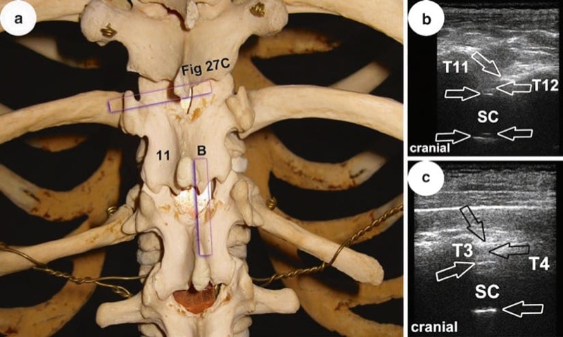
Fig. 28 (a) Scanning plane of US image in (b) relative to lower part of TS; posterior view. Eleven marks lamina of thoracic vertebra T11. In (b) and (c), T11 and T12 as well as T3 and T4 mark laminae of respective vertebrae; demonstration of vertebral canal with spinal cord, SC, in paramedian longitudinal scans; arrows point – from superficial to deep – at yellow ligament (double contour!), epidural space (EDS), dorsal (and ventral) surface of dural sac, posterior longitudinal ligament. (See text for more details)
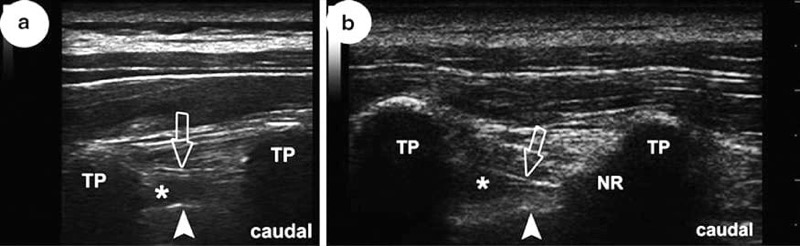
Fig. 29 (a) and (b) Longitudinal scans between transverse processes, TP, of vertebrae T4/ T5 and T5/T6, respectively. Open arrows point at superior costotransverse ligament. Note that in (a) the neck of the rib, NR, is not seen! Arrowheads indicate pleura, asterisks in thoracic paravertebral space. (See text for more details)
9. SONOANATOMY OF THE LUMBAR SPINE: SUPERFICIAL
All of the dorsal surface of the lumbar vertebrae can be appreciated with US. Orientation may be achieved in starting in the midline, spinous processes (SP), and walk off laterally over articular processes (AP) until costal processes (CP) are reached (Figs. 30b, c, and 31b). Proper orientation is of particular value when performing medial branch blocks for facet joint pain. The lumbar medial branches lie in tiny little osseofibrous tunnels (roofed by the mamillo-accessory ligament) between the mammillary and accessory processes of a vertebra (Fig. 30a).
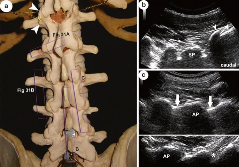
Fig. 30 (a) Scanning planes of US images (a) and (b) relative to LS; posterior view. Arrowheads point at mammillary and accessory processes, yellow line indicates course of lumbar medial branch in between them, circle indicates target point for medial branch block; see Fig. 31. (b) Median longitudinal scan to show (and count) lumbar spinous processes (SP spinous process L5) starting from the median sacral crest (arrowheads). (c) Upper and lower parts demonstrate typical nevertheless different appearances of scans over articular processes, AP, depending on individual anatomy of the LS as well as transducer orientation. Note that white outline of laminae (arrows) in lower image is not continuous throughout (asterisk) due to their waists; compare to upper image. (See text on LS anatomy for more details)
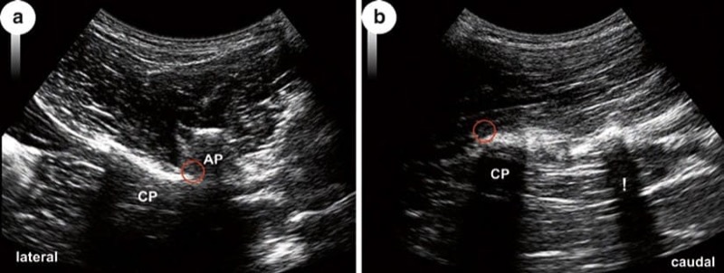
Fig. 31 See Fig. 30a for scanning planes of (a) and (b). (a) Slightly oblique scan to show AP articular processes L1 and L2, CP costal process L2. (b) Lateral longitudinal scan shows typical acoustic shadowing of different widths (!) by costal processes, CP (of L3). Circle indicates target point of medial branch block
This anatomical detail is relevant, as it is one of the reasons why block may fail when done too caudally, especially true when ligament is ossified. Despite the fact that the medial branches themselves are invisible, accuracy of an ultrasound-guided block comes near to fluoroscopy. Often disregarded, however, and apart from the necessity to scan in longitudinal and transverse planes for a meaningful algorithm and optimal orientation, slightly oblique scanning is sometimes helpful, not least due to individually different orientations of CP (Figs. 30a and 31b). It is also noteworthy that, although sometimes proposed, no linear array transducers should be used. This is inappropriate due to both ultrasound physics and given anatomy of the LS and one of the common mistakes made. In contrast, losing orientation in case of very slim and/or short (rudimentary) TP as normal variant is a typical pitfall.
LZJ can be located. It is crucial to understand that these articulations are (1) relatively tight diarthroses with tense ligamentous restriction and that (2) the shape as well as orientation of the articular facets is extremely variable in different people as well as on both sides of a single individual (Fig. 32a and text on LS anatomy). The practical consequence: US-guided LZJ injection should primarily be regarded as periarticular. The hypo- to anechoic gap interrupting the surface outline of articular processes (AP) represents the distance between the posteriormost, bony parts of articulating medial facet and lateral facet of two joining vertebrae. That way, it indicates the dorsal entrance point into a LZJ (Fig. 32b). Under ideal conditions, the covering ligaments (joint capsule) may be visible as hyperechoic structures (Figs. 32b and 33a). The extension of the joint space itself, both radiologic (between bones) and true anatomic (between cartilages), cannot be appreciated with US. In summary, LZJ can be reliably located with US but not imaged to the deep. Apart from that and finally, in case of pathologically altered LZJ, trying to look for a gap with US may be frustrating if simply absent (Fig. 33b).
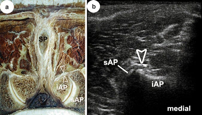
Fig. 32 (a) Transverse section through the lumbar zygapophysial joint, LZJ, between L3 and L4. Spinous process (SP) and inferior articular process (iAP) of L3; superior articular process (sAP) of L4. Note hooked shape of LZJ on the left side compared to the right as well as thickness of capsular ligament (open arrowheads)! (b) Transverse US image corresponding to anatomical cross section in (a) with similar labelling. Note that anechoic gap between bony contours does not represent the true anatomic joint space. (See text for more details)
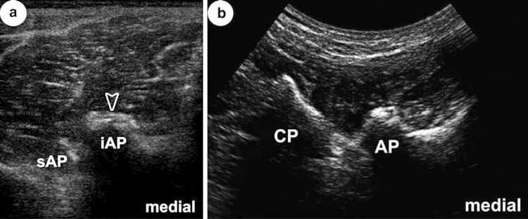
Fig. 33 (a, b) Examples of LZJ entrances in different individuals and conditions. (b) Scanned from lateral and oblique (CP seen) and with curvilinear probe. For labelling, see Fig. 32. Note narrow gap in (a) compared to Fig. 32b. In (b) no gap is seen, but bony surface of AP irregular due to pathologic protuberances. (See text for more details)
10. SONOANATOMY OF THE LUMBAR SPINE: DEEP
To see and interpret structures within the vertebral canal, it is best to use a paramedian longitudinal plane, with spine flexed to widen the acoustic window! Thus, even an approach between laminae of L5 and sacrum is possible (Fig. 34a–c). Moreover, in the lumbar spine, calcified yellow ligaments are less frequent. However, ossification occurs and may hinder US exploration and approach. It is then advisable to look for a median acoustic window between TP, accepting that image quality may decrease significantly (Fig. 35a, b).
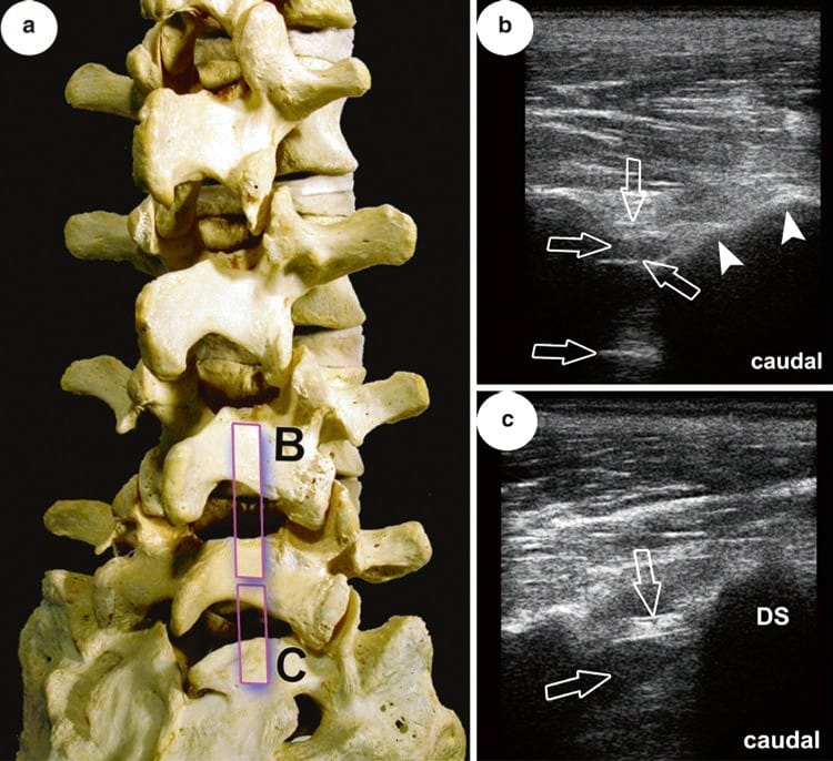
Fig. 34 (a) Scanning planes for US images (a) and (b) relative to the lower part of LS; posterolateral view. Note non-fusion of S1 laminae! (b) and (c) Demonstration of vertebral canal in the segments between laminae L4/L5 and L5/ sacrum, respectively. DS dorsal surface of sacrum; note the orientation of L5 lamina (arrowheads)! Arrows point – from superficial to deep – at yellow ligament (double contour!), epidural space (EDS) (dorsal and ventral) and surface of dural sac. Note the thickness of yellow ligament in the lower segment! (See text for more details)
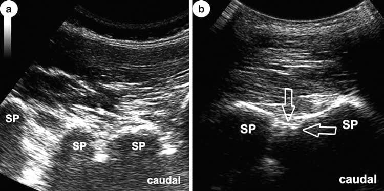
Fig. 35 (a, b) Median longitudinal scans at lower lumbar spine showing influence of maximum flexion (b) in visualisation of the spinal canal. SP spinous processes. Only in (b) structures may be visualised under good conditions, but quality is poor (compared to Fig. 34b). At least yellow ligament and epidurals space can be identified (arrows). (See text for more details)
As windows between CP are relatively wide and laminae very slim, US exploration may reach rather deep, especially when the US probe is positioned “paravertebral” and scan is directed in antero-medial direction. That way, considerable parts of the vertebral bodies (and discs) can be seen (Fig. 36a–c). It is necessary to mention, however, that all of what is said here concerning “deep” is often not feasible in marked obesity.
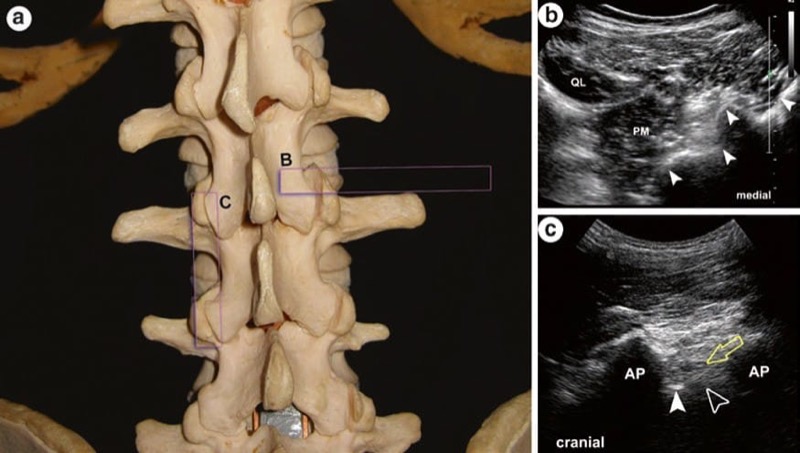
Fig. 36 (a) Scanning planes of US images (a) and (b) relative to LS; posterior view. (b) Transverse image obtained with transducer positioned “paravertebral” and scanning direction to antero-medial. Arrowheads indicate from deep to superficial: anterolateral circumference of vertebral body, lateral margin of interarticular portion, articular process and lamina; QL quadratus lumborum muscle; PM psoas major muscle. (c) Longitudinal scan between two articular processes, AP, immediately adjacent to lamina. Open arrow points at lumbar root L3 exiting intervertebral foramen, arrowhead indicates dorsal surface of vertebral body, open arrowhead indicates intervertebral disc. (See text for more details)
11. SONOANATOMY OF THE SACRUM AND SACROILIAC JOINT: SUPERFICIAL
Excellent images of the dorsal surface of the sacrum are the rule. The dorsal sacral foramina and their ligamentous covering are beautifully seen with US and serve as ideal landmarks for orientation. The same is true for the more prominent sacral crests (Figs. 37a–40c). Clinically we need to identify all of these structures as they guide us to the deeper ones (e.g. trans-sacral block, caudal epidurals or sacroiliac joint (SIJ) injections). Apart from that, by counting these foramina, one may detect sacral elongations that mean incorporation of either lumbar or coccygeal elements. Finally anomalies are readily seen by US (e.g. bifid spine), and all forms of variations and incomplete ossifications may be detected.
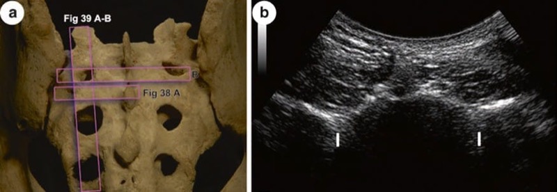
Fig. 37 (a) Scanning levels of US image in (b), for image in Figs. 38a and 39a, b. (b) Overview of dorsal surface in a transverse US scan at the level of posterior sacral foramen I. Note the indentation instead of a crest! (See text for more details)
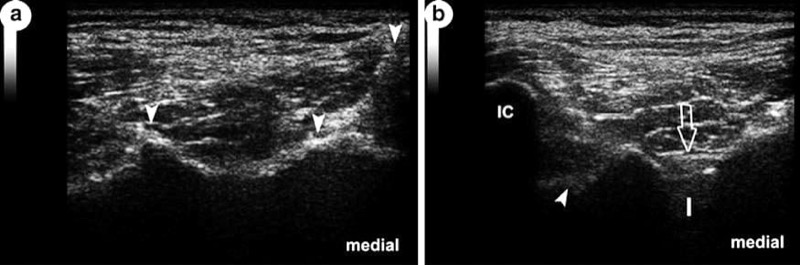
Fig. 38 (a) US visualisation of sacral crests. From median to lateral, arrowheads indicate median, intermediate and lateral sacral crest. Note the marked elevation of lateral crest! (See text for more details). Slightly oblique scan over iliac, IC, and lateral sacral crest at the level of dorsal sacral foramen I. Open arrow shows covering ligaments of foramen; arrowhead points at sacral tuberosity. (See text for more details)
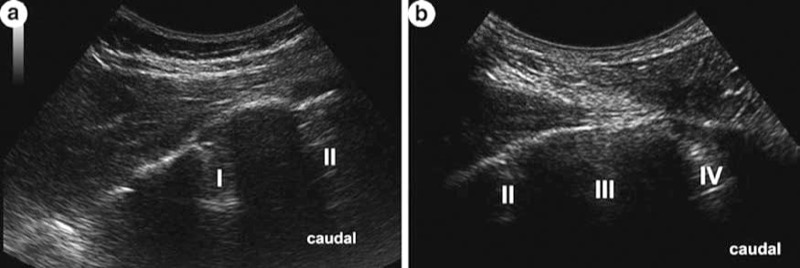
Fig. 39 Both images (a) and (b) show dorsal sacral foramina I–IV. Note their different dimensions and the overall convexity of dorsal sacral surface. (See text for more details)
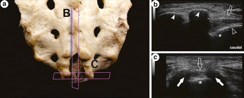
Fig. 40 Scanning planes of US images in (a) and (b); posterior view of the lower third of the sacrum with sacral hiatus. (b) US over end of median sacral crest (arrowheads) and sacral hiatus; the latter is closed in the living by the sacro-coccygeal ligament (open arrow), and asterisk marks bony floor of hiatus; open arrowhead indicates sacro-coccygeal gap. (c) Transverse scan over sacral horns (white arrows). (See text for more details)
12. SONOANATOMY OF THE SACRUM AND SACROILIAC JOINT: DEEP
There is often a misunderstanding or at least confusion concerning the terminology and thus meaning of “SIJ” per definition. This often leads to inappropriate comparisons/judgments of methods described in the literature, especially as far as US approaches are concerned. So for the sake of clarity, what is mainly commented on in the sequel is attributed to the synovial joint or diarthrosis between the ilium and sacrum.
Because it is hidden deep in the pelvic framework for most of its extension, the SIJ articular cavity can only be reached under US guidance when entering the joint space in its most posterior compartment (Fig. 41a, b). However, visualisation of the needle within the joint space cannot be achieved. As there is a potential danger reaching the pelvis and its content through the greater sciatic foramen, correct needle direction and simultaneous demonstration of gluteal surface of the ilium are essential! In cases of partial non-fusion of sacral elements near the midline, the sacral canal may be reached ultrasonographically quite comparable to US-guided epidural approaches elsewhere in the spine (Fig. 42a, b).
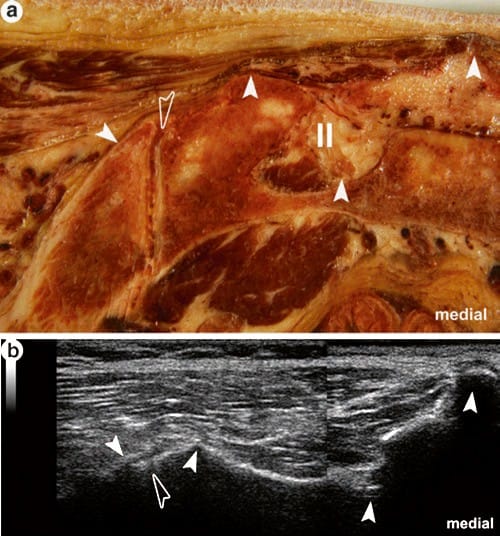
Fig. 41 (a) Transverse section through the posteriormost part of the sacroiliac diarthrosis. The following landmarks (arrowheads) seen on this cross section are detectable in US, see corresponding image in (b) with the same labelling, and their identification is mandatory for safe approaches. From medial to lateral: median sacral crest, second dorsal sacral foramen, lateral sacral crest and gluteal surface of the ilium. The entrance into this part of the joint is very small (open arrowhead). Note the groove between the lateral sacral crest and ilium in the anatomic specimen. If this is the case, it may easily be mistaken ultrasonographically as the joint gap! (See text for more details)
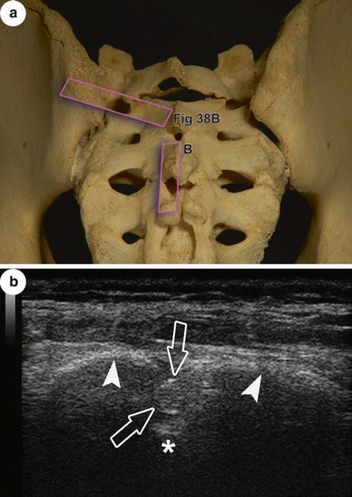
Fig. 42 (a) Scanning planes of US images in (b) and for Fig. 38b; posterior view of a sacrum with incomplete ossification throughout showing “windows” within the dorsal wall of the sacral canal. (b) The bony floor of the sacral canal is clearly seen (above asterisk) as well as the terminal part of the dural sac (open arrows) reaching far caudally in this individual. White arrowheads point at equivalent of vertebral laminae