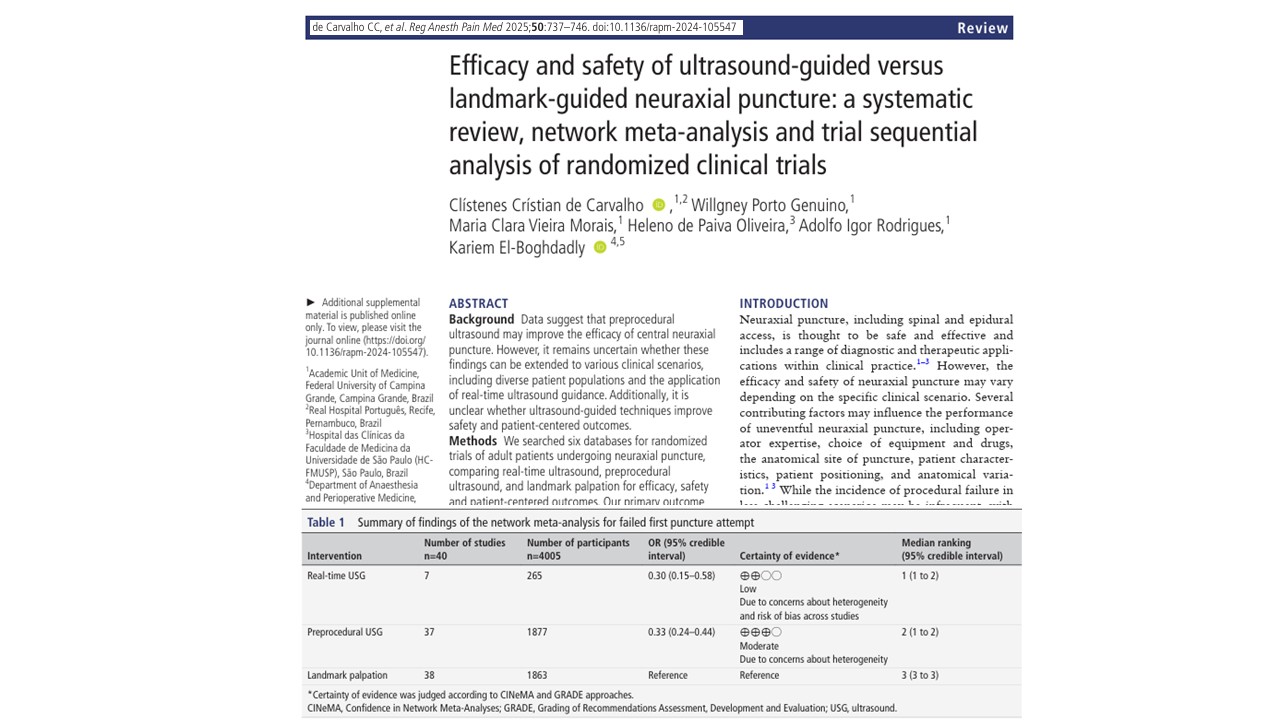
Ultrasound-Guided Third Occipital Nerve and Cervical Medial Branch Nerve Blocks - NYSORA

Explore NYSORA knowledge base for free:

Ultrasound-Guided Third Occipital Nerve and Cervical Medial Branch Nerve Blocks

Anatomy Cervical zygapophyseal (facet) joints are diarthrodial joints formed by the superior articular process of one cervical vertebra articulating with the inferior articular process of the vertebrae above at the level of the junction of the lamina and the pedicle. The angulations of the facet joints increases caudally, being about 45° to the transverse plane at the upper cervical level to assuming a more vertical position at the upper thoracic level. The superior articular process also faces more posteromedial at the upper cervical level, and this changes to more posterolateral at the lower cervical level, with C6 being the most common transition level [1, 2]. Each facet joint has a fibrous capsule and is lined by a synovial membrane. The joint also contains varying amounts of adipose and fibrous tissue forming different types of synovial folds contributing to different pathophysiology for joint dysfunction [3]. The cervical zygapophysial joints are innervated by articular branches derived from the medial branches of the cervical dorsal rami. The C3–C7 dorsal rami arise from their respective spinal nerves and pass dorsally over the root of their corresponding transverse process. The medial branches of the cervical dorsal rami run transversely across the centroid of the corresponding articular pillars and have a constant relationship with the bone at the dorsolateral aspect of the articular pillar as they are bound to the periosteum by an investing fascia and held in place by the tendon of the semispinalis capitis muscle [4]. Variations in the course of the medial branches are usually distributed across the middle fourth of the height of the articular pillars. The articular branches arise as the nerve approaches the posterior aspect of the articular pillar, one innervating the zygapophysial joint above, and the other innervating the joint below. Consequently, each typical cervical zygapophysial joint below C2–C3 has dual innervations, from the medial branch above and below its location. The medial branches of the C3 dorsal ramus differ in their anatomy. A deep medial branch passes around the waist of the C3 articular pillar similar to other typical medial branches and supplies the C3–C4 zygapophysial joint. The superficial medial branch of C3 is large and known as the third occipital nerve (TON). It curves around the lateral and then the posterior aspect of the C2–C3 zygapophysial joint giving articular branches to the joint. Beyond the C2–C3 zygapophysial joint, the TON becomes cutaneous over the suboccipital region. Another anatomical exception is the course of the medial branch C7. The C7 medial branch passes more cranial, closer to the foramen of C7, crossing the triangular superior articular process of C7 vertebrae.


1. INDICATIONS FOR CERVICAL MEDIAL BRANCH BLOCK

Cervical facet joints are important in sharing the axial compressive load on the cervical spine along with the intervertebral disk, particularly at higher compressive loads [5]. The facet joint and capsule are also important contributors to the shear strength of the cervical spine and resection; displacement or even facet capsular disruption increases cervical instability [6, 7].

The facet joint and capsule are in close proximity to the semispinalis, multifidus, and rotator neck muscles, and about 23% of the capsule area provides insertion of these muscle fibers contributing to injury with excessive muscle contraction [8, 9]. The facet joint and capsule also have been shown to contain nociceptive elements suggesting that they may be an independent pain generator [10]. Facet joint degeneration occurs in the elderly almost ubiquitously [11], and the prevalence of facet joint involvement in chronic neck pain has been reported from 35% to 55% [12, 13], making it an important target of interventional pain management.

Cervical facet joint nerve blocks are indicated in axial neck pain not responsive to conservative therapy and with clinical and/or radiological evidence of possible facet joint involvement. The whiplash-associated disorder is a special condition among neck pain patients and a common consequence of different traumatic events, such as car accidents. Excessive facet joint compression and capsular ligament strain have been implicated in neck pain after whiplash injury [14]. Conservative treatment of chronic neck pain following whiplash injury often has poor long-term outcome [15]. Among the possible reasons for this is that an anatomical diagnosis is not made and that treatment does not specifically target the source of pain. Since reliable clinical or radiological signs to identify the responsible joints are lacking, diagnostic blocks of the cervical medial branches are the only validated method to diagnose zygapophysial joint pain [16, 17]. Because the false-positive rate of a single block is 38% [18], a second confirmatory block should be performed on a different day to minimize the chance of obtaining a false-positive response [19]. If diagnostic blocks are used, the source of the pain can be traced to one or more of the cervical zygapophysial joints in over 50% of patients [20]. These patients can then be treated by percutaneous radiofrequency neurotomy. Radiofrequency neurotomy, introduced in 1980 by Sluijter and Koetsveld-Baart [21], has ever since been validated as a very effective therapy for zygapophysial joint pain [22]. Radiofrequency neurotomy is indicated only if a positive response is obtained after both injections. Third occipital neurotomy has been validated as an effective treatment for headache stemming from the C2–C3 zygapophysial joint and mediated by the TON [23]. Furthermore, a recent study showed a positive effect of repetitive therapeutic medial branch blocks with or without steroids [24].


2. WHY ULTRASOUND-GUIDED FACET NERVE BLOCK? THE LITERATURE AND OUR EXPERIENCE

In a study on volunteers, we demonstrated that it is possible to visualize and block the TON [25].

Typically, the diagnostic blocks are performed under fluoroscopic (or CT) control. However, the nerves are not visualized by either fluoroscopy or CT. In our study, we tested the hypothesis that the TON, which innervates the C2–C3 zygapophysial joint and a small skin area, can be visualized by ultrasound and also blocked by injecting a local anesthetic under ultrasound control. The region of the C2–C3 joint was investigated by ultrasound in 14 healthy volunteers, using a 15-MHz transducer. The injection of saline or local anesthetic was performed in a double-blind, randomized fashion. The position of the needle was controlled by fluoroscopy. Sensations at the innervated skin area were tested by pinprick and cold. In all 14 volunteers, the cervical ultrasound examination was feasible, and the TON was successfully visualized in 27 of 28 cases. In most cases, the TON was seen as an oval hypoechoic structure with hyperechoic small spots inside. This is typical for the ultrasound appearance of a peripheral nerve [26, 27].

The median diameter of the TON was 2.0  mm (range, 1.0–3.0), and the nerve was found at a median depth of 20.8  mm (range, 14.0–27.0). Anesthesia of the skin was achieved in all but one case, while no anesthesia was observed after all saline injections. The radiological analysis of the needle positions showed that we localized the C2–C3 zygapophysial joint correctly in 27 of 28 cases and revealed that 23 of 28 needle placement were correct (82%). Although in the abovementioned study, we reported the feasibility of identifying the TON, there are no other feasibility studies regarding ultrasound-guided lower cervical medial branch block. Nevertheless, the technique has been described [28, 29].

The question regarding the sonographic visibility of all the facet joint supplying nerves is currently being examined in our pain unit, with promising results so far (Siegenthaler et al. unpublished data). In patients suffering from chronic neck pain, the sonographic visibility of the cervical medial branches was described and classified as good in the vast majority of cases. The only exception was the C7 medial branch, which is much more difficult to visualize. The reason for this may be that the C7 medial branch is superimposed by a thicker layer of soft tissue than the medial branches situated more cranially and/or its slightly different anatomical course. The nerves are only about 1–1.5 mm in diameter, the needed high-ultrasound frequency to generate enough resolution to determine such small structures may, therefore, in the case of the medial branch C7, not penetrate enough to the target.


3. POSSIBLE ADVANTAGES OF ULTRASOUND FOR CERVICAL FACET NERVE BLOCKS

Medial branch blocks are usually performed under fluoroscopic control; however, few pain physicians use computer tomography (CT) as well. The center of the rhomboid-shaped articular pillars (or the superior articular process in the case of C7) serves as bony landmarks and can be easily identified fluoroscopically in a lateral view. There, the medial branches are located in a safe distance from the spinal nerve, and the vertebral artery and a needle can be introduced to block the nerves (according to the abovementioned bony landmarks only). Because several blocks are often needed to identify the symptomatic joint or to rule out zygapophysial joint pain, the procedure may expose patients and personnel to considerable radiation doses [30]. In contrast, ultrasound is not associated with exposure to radiation.

Ultrasound can identify muscles, ligaments, vessels, joints, and bony surfaces. Importantly, thin nerves can be visualized, provided that high-resolution transducers are applied. This characteristic is not shared by either fluoroscopy or CT and is the major reason for the great potential use of ultrasound in interventional pain management. Unlike fluoroscopy and CT, ultrasound does not expose patients and personnel to radiation. Imaging can be performed continuously. The fluid injected is mostly visualized in a real-time fashion. Therefore, if the target nerve is identified, ultrasound provides the unique opportunity to assure the spread of the injected solution at the site of the block during administration, without radiation exposure and the need of contrast dye injection. Vessels are visualized most clearly when Doppler sonography is available. Thus, the risk of intravascular injection of local anesthetics or injury of vessels is minimized. Ultrasound is less expensive than CT and, depending on the type of device, may be less expensive than fluoroscopy


4. LIMITATIONS OF ULTRASOUND

The major limitation of ultrasound is the poor visualization of thin needles. However, the movements of the tissues while advancing the needle provide experienced practitioners with reliable information on the needle tip position. Since bones reflect the ultrasound waves, structures located behind, for example, osteophytes, are not reliably visualized with ultrasound. The use of high-frequency transducers is mandatory to achieve the appropriate resolution to identify small nerves. However, the higher the used frequency, the lower the ultrasound beam will penetrate into the tissue (possible working depth is limited). This means that it is not possible to visualize thin nerves deeper than a few centimeters from the surface.


5. ULTRASOUND-GUIDED TECHNIQUE FOR TON AND CERVICAL MEDIAL BRANCH BLOCK

Scanning Before Injection

The patient is placed in the left or right lateral position. Usually, we perform an ultrasound examination to identify all important structures prior to the disinfection of the skin and wrapping the ultrasound transducer with a sterile plastic cover.


6. IDENTIFYING THE CORRECT LEVEL: METHOD 1

Using high-resolution ultrasound imaging (we use a Sequoia 512® Ultrasound System with a 15-MHz high-resolution linear ultrasound transducer, 15L8w, Acuson Corporation, Mountain View, CA), the ultrasound examination is started with the cranial end of the transducer over the mastoid process almost parallel to the underlying spine in a longitudinal plane (Fig.1). Moving the transducer slowly anterior and posterior (to the mastoid) and some millimeter more caudally, the most superficially situated bony landmark of the upper cervical spine, i.e., the transverse process of C1, is visualized. With slight rotations of the transducer, the transverse process of C2, about 2 cm more caudally, is searched in the same ultrasound image. All these three bony landmarks are relatively superficial (depending on the habitus of the patient) and produce a bright reflex with the typical dorsal shadowing of bony structures. Between the transverse processes of C1 and C2, 1–2 cm deeper, the pulsation of the vertebral artery can be seen. At this stage, the use of Doppler sonography may facilitate the identification of this important landmark. The vertebral artery crosses the anterior lateral part of articulation of C1–C2 at this position.

Fig.1 To identify the facet joint C2–C3, the ultrasound examination is started with the cranial end of the transducer over the mastoid process almost parallel to the underlying spine in a longitudinal plane. The blue rectangle shows the transducer position in relation to the underlying spine at this starting point

Moving the transducer about 5–8 mm more posteriorly, the arch of the atlas (C1) and the articular pillar of C2 (cranial part of the facet joint C2–C3) in the caudal third of the image are visualized (transducer position as shown in Fig. 2). Now the transducer, still longitudinal in relation to the neck, can be moved caudally to bring the C2–C3 and C3–C4 articulations into the center of the ultrasound picture. The approximate position of the ultrasound transducer at this point is illustrated in Fig. 3, and the obtained ultrasound image is shown in Fig. 4. Slight rotatory movement of the transducer is needed to identify the TON crossing the articulation of C2–C3 at this point. Because it is known that the TON crosses the C2–C3 zygapophysial joint in this plane at an average distance of 1 mm from the bone [31], we search for the typical sonomorphological appearance of a small peripheral nerve at this location. A peripheral nerve crossing the ultrasound plane at an angle of approximately 90°, as in the present case, can be identified better than one running longitudinally along the plane of view. It appears typically as an oval hypoechoic area with hyperechoic spots encircled by a hyperechoic horizon [26, 27, 32].

Fig. 2 From the transducer position shown in Fig. 1, the transducer is moved about 5–8 mm more posteriorly to the position shown in this image. Know the arch of the atlas (C1) and, in the caudal third of the image, the articular pillar of C2 can be visualized

Fig.3 The final position of the transducer in relation to the underlying cervical spine for the identification of the C2–C3 facet joint. The movements of the transducer from the position in Fig.1 to the final position in Fig.3 are described more extensively in the text

Fig.4 Image obtained by a transducer position as shown in Fig.3. The third occipital nerve crosses the articulation of C2–C3, and the medial branch of C3 crosses at the deepest point between the articulations C2–C3 and C3–C4. The nerves can be seen with a typical sonomorphological appearance: an oval hypoechoic (black) structure with hyperechoic (white) small spots inside and a hyperechoic horizon around it

Reverse Ultrasound Anatomy illustration of figure 4. MB, medial branch.

The more caudal cervical medial branches are searched in the same way. Once we have identified the articulation of C2–C3, the transducer is slowly moved in a caudal direction.

Starting at C2–C3 we count the “hills” by moving the transducer—still in longitudinal direction in relation to the neck—caudally until we reach the desired level of the cervical facet joint. With a transducer position as shown in Figs. 5 and 6, you will obtain an image of the level C3– C4 and C4–C5 as shown in Fig.7. Bringing the articulation into the center of the ultrasound picture, we are able to visualize the two medial branches innervating the joint. Only the C2–C3 joint is innervated by one single nerve (the TON). All articulations more caudal are innervated by two medial branches, arising out of the two roots, one cranial and one caudal of the articulation. Unlike the TON, the medial branches do not cross over the highest point of the articulation, but at the deepest point of the corresponding articular pillar from anterior to posterior between two articulations, and are visualized there (Fig.7).

Fig.5 The transducer position to obtain the image in Fig.7 in relation to the underlying cervical spine is shown

Fig.6 The transducer position in relation to the neck to obtain the image in Fig.7 is shown

Fig.7 Typical white (hyperechoic) reflex of the bony surfaces of the articulations C3–C4 and C4–C5. The medial branch C4 (MB C4) can be seen at the deepest point between the articulations C3–C4 and C4–C5, nearly in contact to the bone. The medial branch C5 (MB C5) is seen at the deepest point of the bony surface more caudally of the articulation C4–C5


7. IDENTIFYING THE CORRECT LEVEL: METHOD 2

Especially in the lower cervical spine, it is a good alternative to count and identify the roots in the interscalene region and then follow them to the corresponding osseous cervical level. If the visualization of the roots is difficult, first identifying the transverse processes of C5, C6, and C7 may help as anatomic landmarks to find the roots and then follow them more distally. Usually, the C6 transverse process is the most prominent one, showing impressive anterior and posterior tubercles (U-shaped) and dorsal shadowing from the bone. Between the two tubercles the anterior part of the nerve root can be seen. Following this root distally one can identify the interscalene region, even if the two interscalene muscles are hardly identified by ultrasound.

At the level of C7, the anterior tubercle is absent and the vertebral artery is usually seen slightly anterior of the root. Figure 8 shows the transducer position to obtain an ultrasound image of the root C7 and the vertebral artery (Fig.9a). The use of color Doppler is recommended to better identify the vertebral artery (Fig. 9b). This will help to identify the correct vertebral level and corresponding nerve root, but one must be aware of the possible anatomical variation.

It may be helpful to mark the skin at the level of interest to improve the successful identification of the structures after sterile preparation of the work field and the transducer.

Fig.8 Transducer position to scan the root C7 as shown in Fig.9a, b for the identification of the vertebral level

Fig.9 (a) Ultrasound image of the root C7 and the vertebral artery some millimeters anteriorly of the root. Asterisk root C7, VA vertebral artery, TPT posterior tubercle of the transverse process of C7. (b) The same ultrasound image as Figure a with the use of Doppler ultrasound


8. PRACTICAL PERFORMANCE OF BLOCK

After scanning the neck and identifying the targeted nerves, the skin is disinfected, the transducer is wrapped in a sterile plastic cover, and sterile ultrasound coupling gel is used. The needle is introduced from immediately anterior to the ultrasound probe and slowly advanced perpendicular to the beam (“short axis”) as shown in Fig. 10. We use a short bevel 24-G needle connected over an extension line to a syringe. Injection is performed by a second person holding the syringe. The needle tip is advanced until it is seen to lie just beside the nerve. At this point, increments of 0.1 ml of local anesthetic (LA) are injected, until it reaches the nerve adequately. If necessary, the needle tip is slightly repositioned. The conventional, fluoroscopically guided technique for TON blocks requires needle placements onto three target points, each injected with 0.3 ml (total 0.9 ml) of LA. Our experience showed that using ultrasound guidance 0.5 ml is enough to block the TON.  To block the other medial branches, usually 0.3 ml of LA is sufficient. The total volume needed is dependent on the spread of LA. We recommend injecting no more than 0.5 ml of LA per nerve, since higher volumes would lower the specificity of the block because of potential anesthesia of other pain relevant structures near the medial branch.

Fig.10 Needle and transducer relationship to perform an ultrasound- guided cervical medial branch block at the level of C4–C5. The transducer is positioned longitudinal to the neck, and the needle is introduced immediately anterior to the ultrasound probe and slowly advanced

We always introduce the needle from anterior to posterior because all vulnerable structures are situated more anterior to the facet joint line (i.e., vertebral artery and neuroforamen). This lowers the risk of inadvertent puncture of these structures in case the needle tip is not correctly identified. Nevertheless, this procedure is not recommended for people not experienced in ultrasound-guided injections and should be performed only after adequate needle guidance experience and training. As we gain more experience in identifying the course of the nerves by ultrasound, ultrasound-guided radiofrequency ablation (RFA) will become feasible, and this may reduce the needed number of lesions. Furthermore, it is possible to bring the RF probes close to the nerve with ultrasound guidance prior to taking an X-ray image, thus reducing the radiation exposure.


9. CONCLUSION

This overview illustrates the potentially useful application of ultrasound and describes the technique of TON and cervical medial branch blocks. In contrast to fluoroscopy and CT, ultrasound allows visualization of the cervical medial branches in most patients, and thus the local anesthetic can be injected as close as possible to the targeted nerve. However, ultrasound has limitations. Depending on the habitus of patients, it is not possible to visualize the very small nerves in all cases, especially at the C7 level.

Ultrasonography of nerves as small as the cervical medial branches requires excellent anatomical knowledge and experience. The identification of the nerves is frequently difficult. Therefore, adequate training is mandatory before ultrasound is used for this procedure. Lack of training can make the procedure ineffective and unsafe, especially in the neck area which is packed with several vital nearby structures.

Further research in the field should provide evidence that ultrasound is at least equivalent or superior to traditional imaging techniques as fluoroscopy or CT in terms of effectiveness and safety of diagnostic or therapeutic cervical facet nerve interventions.

Atlas of Ultrasound-Guided Procedures in Interventional Pain Management

PRACTICAL

Learn with Step-by-Step guide by the leading USPM experts

BE INSPIRED

Memorize ultrasound patterns with visual aids and create your own scripts with NOTES tool and never loose them.

UNDERSTAND

Every important aspect of ultrasound-guided pain interventions

READ OR LISTEN.

Learn according to your study style. Read or listen to the voiced-over material.

GENICULAR BLOCKS, SPINAL ULTRASOUND AND NEURAXIAL INTERVENTIONS