


Thoracic paravertebral block (TPVB) is the technique of injecting local anesthetic alongside the thoracic vertebral body close to where the spinal nerves emerge from the intervertebral foramen. This produces unilateral (ipsilateral), segmental, somatic, and sympathetic nerve block in multiple contiguous thoracic dermatomes [1, 2], which is effective for managing acute and chronic pain of unilateral origin from the thorax and abdomen [3]. Recently, TPVB has also been used for surgical anesthesia in patients undergoing inguinal herniorrhaphy [4] and breast surgery [5, 6] with improved postoperative outcomes [3].
1. ANATOMY
The thoracic paravertebral space (TPVS) is a wedge-shaped space located on either side of the vertebral column (Fig. 1) [3]. Anterolaterally it is bound by the parietal pleura (PP), while the superior costotransverse ligament (SCL), which extends from the lower border of the transverse process above to the upper border of the transverse process below, forms the posterior border (Figs. 1 and 2) [3]. The base of the wedge is formed by the posterolateral surface of the vertebral body, intervertebral disk, and the intervertebral foramen with its contents [3]. Interposed between the PP and the SCL is a fibroelastic structure, the “endothoracic fascia,” [3, 7, 8] which is the deep fascia of the thorax (Figs. 1, 2, and 3) [3, 7, 8] and lines the inside of the chest wall. A layer of loose areolar tissue, the “subserous fascia,” is present between the PP and the endothoracic fascia (Figs. 1 and 2) [3, 7].
The endothoracic fascia thus divides the TPVS into two potential fascial compartments, the anterior “extrapleural paravertebral compartment” and the posterior “subendothoracic paravertebral compartment” (Fig. 1). The TPVS contains fatty tissue within which lie the intercostal nerve, the dorsal rami, the intercostal vessels, and the sympathetic chain. The TPVS communicates with the contiguous space above and below, the epidural space medially, the intercostal space laterally, the contralateral paravertebral space via the prevertebral and epidural route, and inferiorly (the lower TPVSs) with the retroperitoneal space posterior to the fascia transversalis via the medial and lateral arcuate ligaments [3, 8, 9]. The cranial extension of the TPVS is still not defined, but we have observed spread of radiocontrast medium to the cervical paravertebral region on chest radiograph after thoracic paravertebral injection.
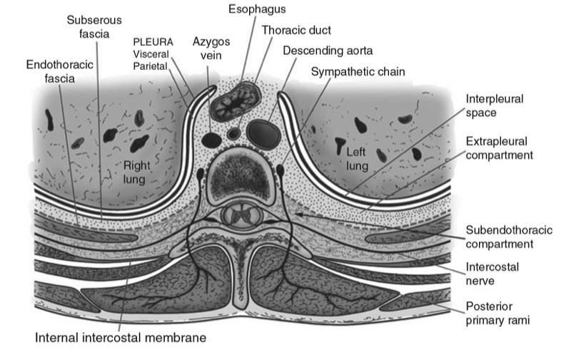
Fig. 1. Anatomy of the thoracic paravertebral space (TPVS).
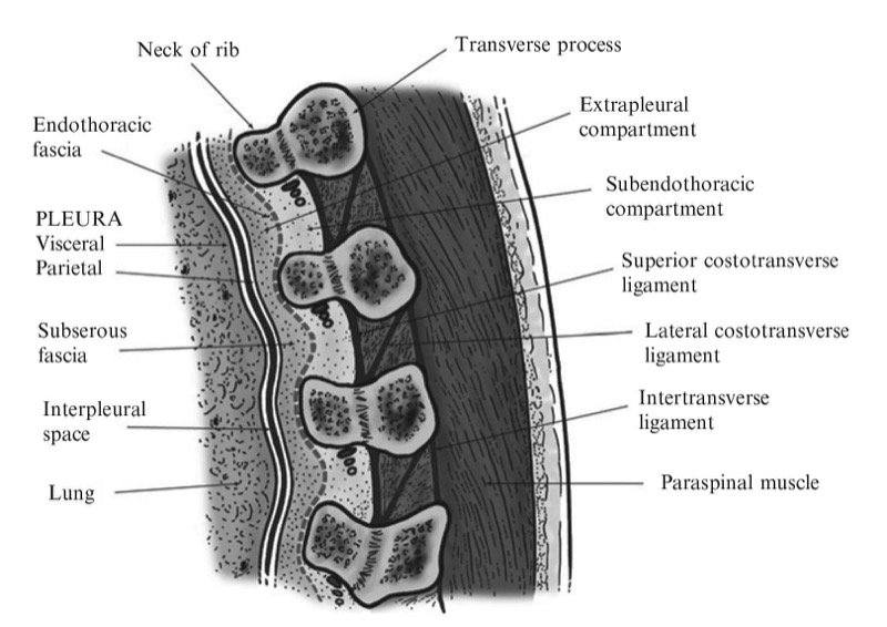
Fig. 2. Sagittal section through the TPVS.
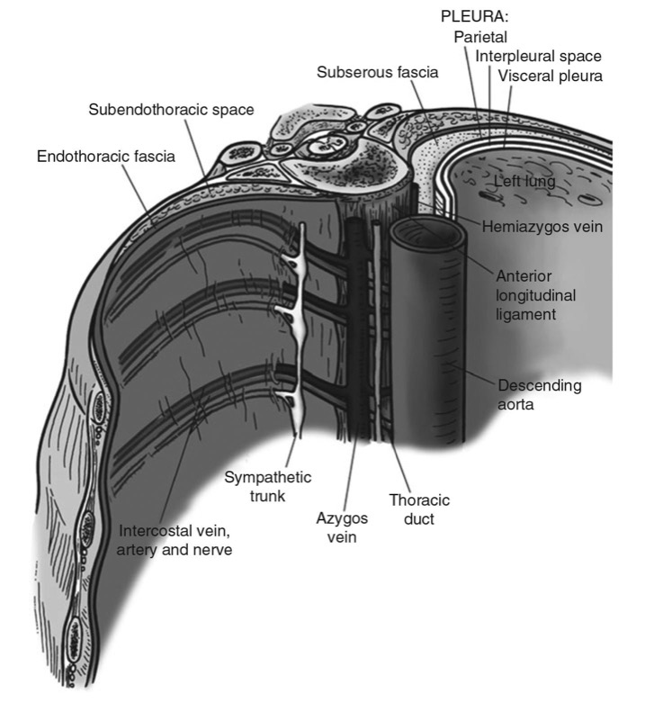
Fig. 3. The endothoracic fascia and its relations to the TPVS.
2. MECHANISM OF block
The exact mechanism by which a thoracic paravertebral injection produces ipsilateral, segmental, thoracic anesthesia and analgesia is still not clear. A thoracic paravertebral injection may remain localized to the space injected [10], or it may spread to contiguous spaces above and below [8, 11, 12], the intercostal space laterally [3, 11–13], the epidural space medially [11, 13], or a combination of the above [3]. This is how the ipsilateral somatic and sympathetic nerves, including the posterior primary ramus, at multiple contiguous thoracic levels are affected [3]. The role of epidural spread in the extension of sensory block after thoracic paravertebral injection is still not clear. Varying degrees of epidural spread have been shown to occur in majority (70%) of patients [13]. However, the volume of injectate that enters the epidural space is only a small fraction of the total injectate [12] and confined to the side of the injection [13]. Sensory block is also unilateral and greater after epidural spread than after paravertebral spread only [13]. Current evidence therefore suggests that epidural spread after thoracic paravertebral injection contributes to the extension of a TPVB [3].
3. TECHNIQUES OF TPVB
There are several different techniques of performing TPVB, and it can be performed with the patient in the sitting, lateral decubitus (with the side to be blocked uppermost), or prone position [3]. The technique that is most frequently used involves eliciting “loss of resistance.” [14] At the appropriate dermatome under aseptic precautions, a 22-G Tuohy needle (for a single-shot injection) or a 18- or 16-G Tuohy needle, if a catheter is to be inserted, is introduced 2.5 cm lateral to the highest point of the spinous process and advanced perpendicular to the skin in all planes until the transverse process is contacted. For safety, it is imperative to locate the transverse process before the needle is advanced any further to avoid deep needle insertion and possible inadvertent pleural puncture. Once the transverse process is located, the needle is withdrawn to the subcutaneous tissue and readvanced in a cephalad direction to pass through the space between the two transverse processes until loss of resistance is elicited as the needle traverses the SCL, usually within 1.5–2 cm from the transverse process. Occasionally a subtle pop may also be felt. Unlike epidural space location, the loss of resistance felt as the needle enters the TPVS is subjective and indefinite [14–16]. More often it is usually a change of resistance rather than a definite give. It is the author’s experience that the loss of resistance is best appreciated if one uses a glass syringe filled with air. Luyet et al. [17] have recently demonstrated the presence of a gap between the medial and lateral portions of the SCL in cadavers, which they propose is a possible reason for not being able to elicit a loss of resistance in all cases [17].
Alternatively for TPVB the block needle may also be advanced by a fixed predetermined distance (1–2 cm) once the needle is walked of the transverse process without eliciting loss of resistance [18]. This variation has been used very effectively with minimal complications including pneumothorax [18]. Other techniques that have been used to perform TPVB include “the medial approach,” “pressure measurement technique,” “paravertebral-peridural block,” “fluoroscopy guidance,” and “paravertebral catheter placement under direct vision at thoracotomy.” [3] It is not known whether advancing the needle superior to or inferior to the transverse process affects the overall extent and quality of TPVB [3].
4. ULTRASOUND-GUIDED TPVB
TPVB is traditionally performed using surface anatomical landmarks, and although it is a blind technique, it is technically simple [3] and has a high success rate [3, 5, 19, 20], and the overall complication rate is relatively low [3, 5, 19–21]. Recently, there has been an increase in interest in the use of ultrasound for peripheral [22–24] and central neuraxial blocks [25–27]. However, data on the use of ultrasound for TPVB are limited with only a few publications on the subject to date [17, 28–32].
Pusch et al. [32] used ultrasound to measure the distance from the skin to the transverse process and pleura in women who were scheduled to receive a single-shot TPVB at T4 for breast surgery and found a good correlation between needle insertion depth from the skin to the transverse process and that measured using ultrasound [32]. They also found a good correlation between ultrasound-measured distance from the skin to the PP and the eventual distance from the skin to the paravertebral space that was measured after needle placement [32]. Hara et al. were the first group to describe ultrasound-guided (USG) TPVB (single shot), which they successfully performed in 25 women undergoing breast surgery [31]. They performed a sagittal scan over the paravertebral area at the T4 level and were able to delineate the transverse processes, the ligaments (intertransverse and costotransverse ligaments), and the pleura and were also able to measure the distance from the skin to these structures before block placement [31]. The block needle was inserted, under ultrasound guidance, in the short axis of the ultrasound beam (out-of-plane technique) until it contacted the transverse process [31]. Loss of resistance to saline was then elicited by advancing the needle above the transverse process, without ultrasound guidance, and the spread of the local anesthetic injection was visualized in real-time using ultrasound [31]. Hara et al. report turbulence at the level of the injection in all (100%) cases and forward displacement of the parietal pleura in four (16%) cases [31]. Since all the injections resulted in a successful block, these sonographic changes may be considered as objective evidence of a correct paravertebral injection during USG TPVB. Another interesting observation that Hara et al. made in their cohort of patients is that while they were able to delineate the parietal pleura at the T4 level in all their patients, it was not possible to do so at the T1 level in any patient [31]. The exact reason for this difference is not clear but may be related to the greater depth to the paravertebral space in the upper thoracic region compared to the mid-thoracic region [33] and the use of high-frequency ultrasound which lacks penetration and thus lacks the ability to visualize structures at a depth such as the pleura. Future research should investigate whether low-frequency ultrasound, which penetrates deeper into tissues, can circumvent this problem in the upper thoracic region.
Luyet et al. recently described a cadaver study in which they investigated the feasibility of performing USG TPVB and catheter placement [17]. The authors performed a sagittal scan of the paravertebral region at the mid-thoracic level (T4–T8) using low-frequency ultrasound (2–5 MHz) [17]. They were able to delineate the underlying paravertebral anatomy (transverse process, costotransverse ligament, and pleura) and observed that the best views of the paravertebral anatomy were obtained with the transducer tilted slightly obliquely, i.e., with the upper part of the transducer directed slightly medially in the sagittal axis [17]. An 18-G Tuohy needle was then inserted in the plane of the ultrasound beam (in-plane technique) and advanced under ultrasound guidance to the TPVS [17]. Correct position of the needle in the paravertebral space was confirmed by injecting saline and observing distension of the paravertebral space [17], similar to that reported by Hara et al. [31] A catheter was then inserted through the Tuohy needle, and 10 ml of a dilute contrast medium was injected via the catheter, after which axial CT scans of the thoracic spine was performed. The catheter itself could not be visualized, and various types of contrast spread were noted on the CT scans: paravertebral, epidural (only), intercostal, prevertebral, and pleural [17]. The incidence of pleural puncture (5%) with the US technique described [17] appears to be higher than that reported after landmark-based techniques (pleural puncture 1.1%) [21]. However, before we make any conclusion, we must bear in mind that this was a cadaver study and the results may not translate into clinical practice. Further clinical research evaluating the technique of USG paravertebral catheter placement as described by Luyet et al. [17] is warranted.
Shibata and Nishiwaki [30] and Ben-Ari et al. [28] describe an intercostal approach to the paravertebral space. While there are minor differences in the two approaches described above [28, 30], it basically involves performing a transverse scan of the paravertebral region with a high-frequency linear transducer at the desired level and advancing the block needle from a lateral to medial direction in the plane of the ultrasound beam [28, 30] until the tip of the block needle is confirmed to be in the apex of the TPVS [28, 30]. On a transverse sonogram, the apex of TPVS is identified as a wedge-shaped hypoechoic space between the hyperechoic parietal pleura anteriorly and the internal intercostal membrane posteriorly and is continuous laterally with the posterior intercostal space [30]. Therefore, local anesthetic injected into the posterior intercostal space can spread medially to the TPVS. A correct injection is confirmed by observing anterior displacement of the parietal pleura [28, 30] and widening of the apex of the TPVS. Shibata and Nishiwaki [30] suggest that since the block needle is inserted tangential to the pleura, this technique should reduce the risk of pleural puncture [30]. However, it is our experience that this approach causes significant pain and discomfort to the patients during needle insertion, particularly when one performs the multiple injection TPVB for breast surgery despite using a fine bore block needle (22 G). This may be due to the greater distance that the block needle has to traverse before it enters the TPVS when compared to a traditional landmark-based injection. Therefore, one should consider sedation and analgesia for patient comfort when using this approach for block or catheter placement. Moreover, since the block needle is advanced in the direction of the intervertebral foramen, there is need for larger trials to determine the incidence of complications with this intercostal approach because central neuraxial complications after TPVB are more common with a medially directed needle [3].
More recently O’Riain et al. [29] in a cadaver and clinical study described an in-plane technique of performing USG TPVB. A high-frequency linear transducer (10–5 MHz) was positioned at a point 2.5 cm later to the tip of the spinous process in the longitudinal axis producing a paramedian sagittal scan of the TPVS [29]. The authors describe the contiguous transverse processes as two dark lines [29]. The PP was deep to the transverse process and also seen as a hyperechoic structure that moved with respiration [29]. The SCL was less well defined but was seen as a collection of linear echogenic bands interspersed with hypoechoic areas between two contiguous transverse processes [29]. The TPVS was seen as a hypoechoic space between the SCL and PP [29]. For the block, the midpoint of the transducer was positioned midway between two contiguous transverse processes, and a Tuohy needle (18 G) was inserted in-plane and in a cephalad orientation until it traversed the SCL [29]. Saline was injected to confirm the needle position by demonstrating anterior displacement of the PP and to facilitate catheter placement [29]. The authors comment that it was difficult to track the tip of the advancing needle, which they attribute to the acute angle of needle insertion [29]. Nevertheless, they were able to successfully place a paravertebral catheter in eight of the ten attempts in the cadavers, and all patients in the clinical study (n = 9) had evidence of thoracic wall anesthesia and provided postoperative analgesia [29].
Other than the data described above, the author is not aware of any other published data describing the sonoanatomy relevant for TPVB or the technique of performing real-time USG TPVB in the clinical setting. The following section is a summary of the author’s work on USG TPVB.
5. SONOANATOMY RELEVANT FOR TPVB
Basic considerations
An ultrasound scan for TPVB can be performed in the transverse (axial scan) or longitudinal (sagittal scan) axis with the patient in the sitting (author’s preference), lateral decubitus, or prone position. The prone position is useful in patients presenting for a chronic pain procedure when fluoroscopy may also be used in conjunction with ultrasound imaging. Currently, there are no data demonstrating an optimal axis for the scan or the intervention. It is often a matter of individual preference and experience. The transducer used for the ultrasound scan depends on the body habitus of the patient. High-frequency ultrasound provides better resolution than low-frequency ultrasound, but its penetration is poor. Moreover, if one has to scan at a depth using high- frequency ultrasound, then the field of vision is also significantly narrow. Under such circumstances it may be preferable to use a low-frequency ultrasound transducer (2–5 MHz) with a divergent beam and a wide field of vision. The author prefers to use a high-frequency linear transducer (13–6 MHz) for scanning the thoracic paravertebral region because the transverse process, costotransverse ligament, and the pleura in the mid-thoracic region are located at a relatively shallow depth in patients that he cares for in his clinical practice. It is also the author’s practice to perform a scout (preview) scan before the ultrasound-guided intervention. The objectives of the scout scan is to preview the anatomy, identify any underlying asymptomatic abnormality or variation, optimize the image, measure relevant distances to the transverse process and pleura, and identify the best possible location and trajectory for needle insertion. A liberal amount of ultrasound gel is applied to the skin over the thoracic paravertebral region at the level of injection for acoustic coupling prior to the scan, and sterile ultrasound gel must be used during the USG intervention. The ultrasound image is optimized by making the following adjustments on the ultrasound unit: (a) selecting an appropriate preset (small parts or musculoskeletal preset), (b) setting an appropriate scanning depth (4–6 cm), (c) selecting the “general” optimization (mid-frequency range) option of the broadband transducer, (d) adjusting the “focus” to the right depth corresponding to the area of interest, and finally (e) manually adjusting the “gain,” “dynamic range” map, and “compression” settings to obtain the best possible image. Compound imaging and tissue harmonic imaging when available are useful in improving the quality of the images.
Transverse Scan of the Thoracic Paravertebral Region
For a transverse scan of the thoracic paravertebral region, the ultrasound transducer is positioned lateral to the spinous process with the orientation marker directed to the right side of the patient (Fig. 4). On a transverse sonogram, the paraspinal muscles are clearly delineated and lie superficial to the transverse process (Figs. 5 and 6). The transverse process is seen as a hyperechoic structure, anterior to which there is a dark acoustic shadow which completely obscures the TPVS (Fig. 5). Lateral to the transverse process, the hyperechoic pleura that moves with respiration and exhibits the typical “lung sliding sign,” [34] which is the sonographic appearance of the pleural surfaces moving relative to each other within the thorax, is seen. Comet tail artifacts, which are reverberation artifacts, may also be seen deep to the pleura and within the lung tissue and are often synchronous with respiration [34]. A hypoechoic space is also seen between the parietal pleura and the internal intercostal membrane (Figs. 5 and 6), which is the medial extension of the internal intercostal muscle and is continuous medially with the SCL (Fig. 7). This hypoechoic space represents the medial limit of the posterior intercostal space or the apex of the TPVS, and the two communicate with each other (Figs. 5, 6, and 7). Therefore, local anesthetic injected medially into the TPVS can often be seen to spread laterally to distend this space or vice versa; local anesthetic injected laterally into this space can spread medially to the paravertebral space and is the basis of the intercostal approach for USG TPVB [28, 30] where the needle is inserted in the plane of the US beam from a lateral to medial direction (see below, Technique 3). From the scan position described above (i.e., over the transverse process), if one slides the transducer slightly cranially or caudally, it is possible to perform a transverse scan of the paravertebral region with the ultrasound beam being insonated between the two transverse processes. The ultrasound signal is now not impeded by the transverse process or the costotransverse junction, and parts of the parietal pleura and the “true” TPVS can now be faintly visualized (Figs. 6 and 8). The SCL which forms the posterior border of the TPVS is also visible, and it blends laterally with the internal intercostal membrane, which forms the posterior border of the posterior intercostal space (Fig. 8). The communication between the TPVS and the posterior intercostal space is also clearly seen (Fig. 8).
Fig. 4. The orientation of the ultrasound transducer and how the ultrasound beam is insonated during a transverse scan of the thoracic paravertebral region is shown. The transverse process (TP) usually casts an acoustic shadow (represented in black), which obscures the ultrasound visibility of the TPVS. (Picture in the inset shows the position of the ultrasound transducer relative to the spine).
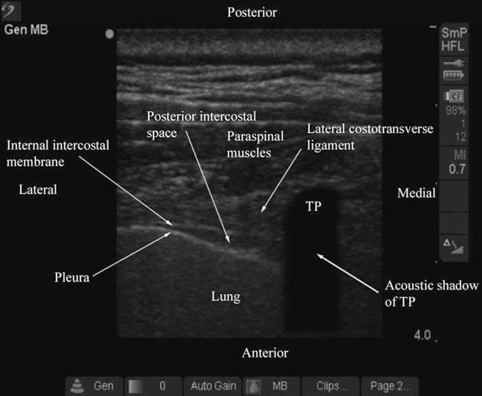
Fig. 5. Transverse sonogram of the thoracic paravertebral region with the ultrasound beam being insonated over the transverse process. (Note how the acoustic shadow of the TP obscures the TPVS. The hypoechoic space between the parietal pleura and the lateral costotransverse ligament and internal intercostal membrane laterally represents the apex of the TPVS or the medial limit of the posterior intercostal space).
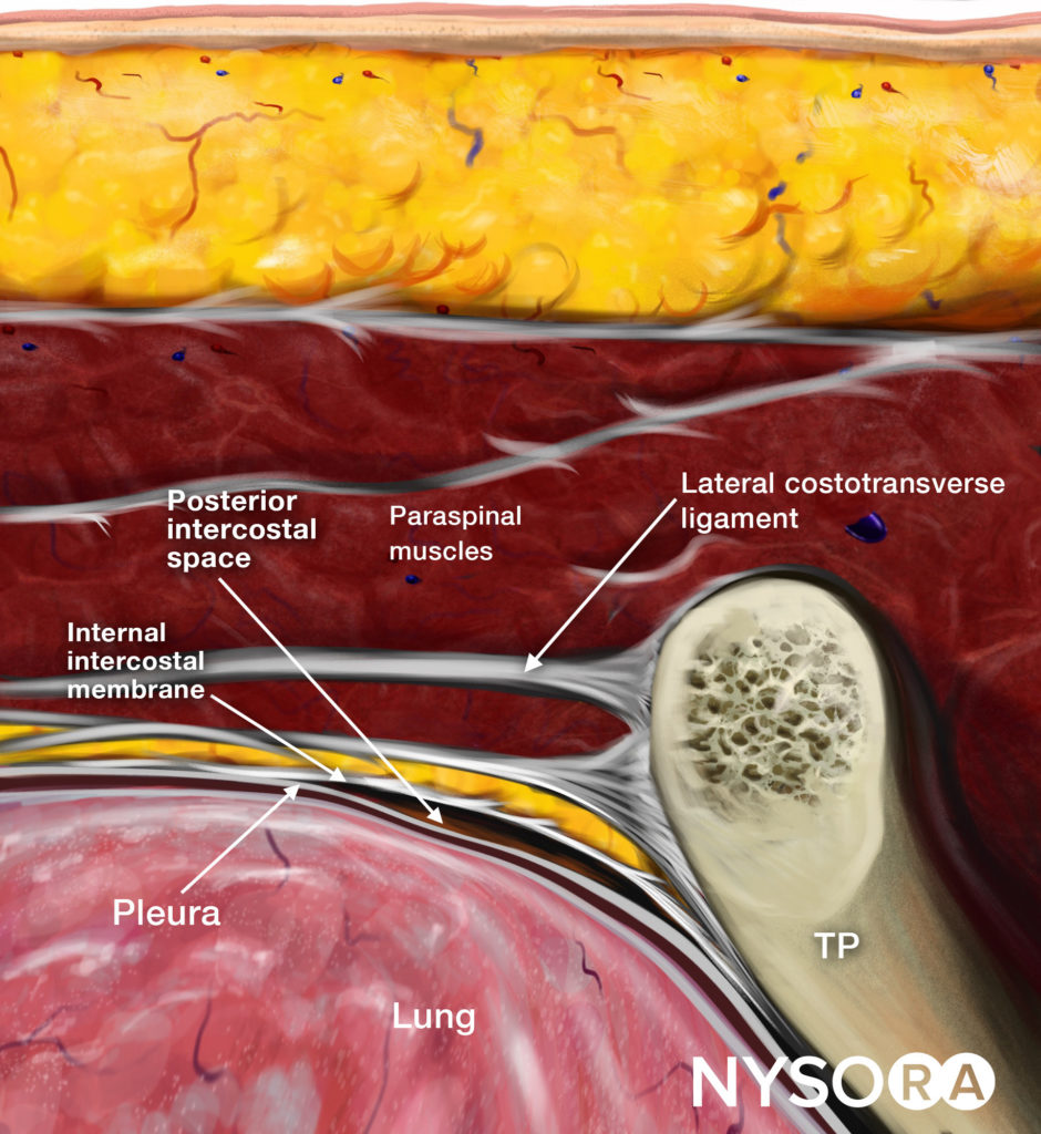
Reverse Ultrasound Anatomy illustration of figure 5. TP, transverse process.
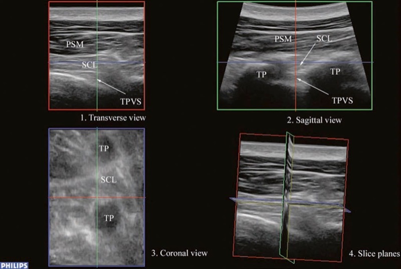
Fig. 6. A multiplanar 3D view of the TPVS. (Note how the three slice planes (red transverse, green sagittal, and blue coronal) are obtained. PSM paraspinal muscles, SCL superior costotransverse ligament, TPVS thoracic paravertebral space, TP transverse process).
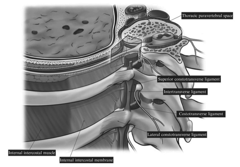
Fig. 7. Anatomy of the thoracic paravertebral region showing the various paravertebral ligaments and their anatomical relations to the TPVS.
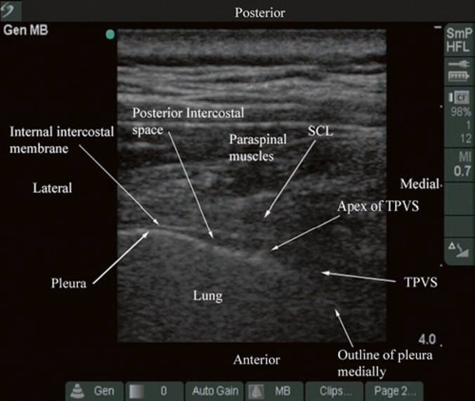
Fig. 8. Transverse sonogram of the thoracic paravertebral region with the ultrasound beam being insonated between two adjacent transverse processes. (Note that the acoustic shadow of the transverse process is now less obvious, and parts of the TPVS and the anteromedial reflection of the pleura are now visible. The superior costotransverse ligament (SCL) which forms the posterior border of the TPVS is also visible, and it blends laterally with the internal intercostal membrane, which forms the posterior border of the posterior intercostal space. The communication between the TPVS and the posterior intercostal space is also clearly seen).
Sagittal Scan of the Thoracic Paravertebral Region
During a sagittal scan of the thoracic paravertebral region, the ultrasound transducer is positioned 2–3 cm lateral to the midline with its orientation marker directed cranially (Fig. 9). On a sagittal sonogram, the transverse processes are seen as hyperechoic and rounded structures deep to the paraspinal muscles, and they cast an acoustic shadow anteriorly (Figs. 10 and 11). In between the acoustic shadows of two adjacent transverse processes, there is an acoustic window produced by reflections from the SCTL and intertransverse ligaments, the paravertebral space and its contents, the PP, and lung tissue (in a posterior to anterior direction) (Figs. 10 and 11). It is the author’s observation that the pleura and the paravertebral space are not clearly delineated in a true sagittal scan (Fig. 9), which may be due to the loss of spatial resolution at the depth or due to “anisotropy,” because the ultrasound beam is not being insonated at right angles to the pleura due to its anteromedial reflection close to the vertebral bodies. In a recent investigation, our group has demonstrated objectively that the ultrasound visibility of the SCL, the paravertebral space, and the pleura is better when the ultrasound beam is insonated in a slightly oblique axis, i.e., with the ultrasound transducer tilted slightly laterally or outward (data to be published) (Fig. 12). The author believes by doing so the ultrasound beam encounters less bony obstruction from the transverse processes and the beam is also more at right angles to the pleura explaining why the paravertebral space and parietal pleura are better visualized (Fig. 12). Therefore, the “paramedian sagittal oblique axis” is in the author’s opinion the optimal axis for sagittal ultrasound imaging of the TPVS. However, this only allows one to visualize the apical part of the paravertebral space. Moreover, with current ultrasound technology, the author has not been able to visualize the intercostal nerve in the paravertebral space, but the intercostal vessels are more readily visible using Doppler ultrasound (Fig. 13).
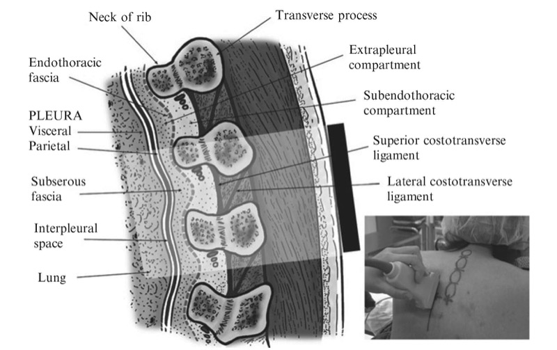
Fig. 9. The orientation of the ultrasound transducer and how the ultrasound beam is insonated during a paramedian sagittal scan of the thoracic paravertebral region is shown. (The picture in the inset shows the position of the ultrasound transducer relative to the spine during the scan).
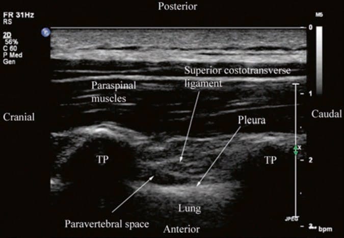
Fig. 10. Paramedian sagittal sonogram of the thoracic paravertebral region. (Note that although the pleura and the TPVS are visible, they are not clearly delineated. TP transverse process).
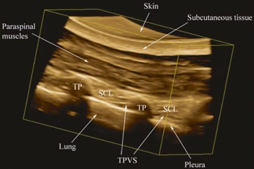
Fig. 11. A rendered 3D view of the TPVS. The acquired 3D volume has been rendered such that the sagittal anatomy of the TPVS is being visualized from the lateral (intercostal space) side. (Note the apical part of the TPVS is clearly delineated between the SCL and the parietal pleura).
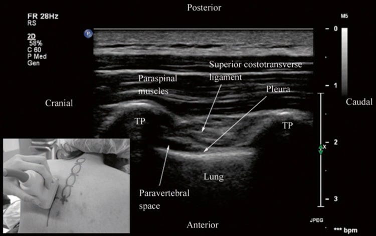
Fig. 12. Paramedian sagittal oblique sonogram of the thoracic paravertebral region. The picture in the inset shows how the transducer is tilted slightly laterally (outward) during the scan. (Note the pleura, SCL, and TPVS are now clearly delineated (same patient as in Fig. 10). TP transverse process, IIM internal intercostal membrane).
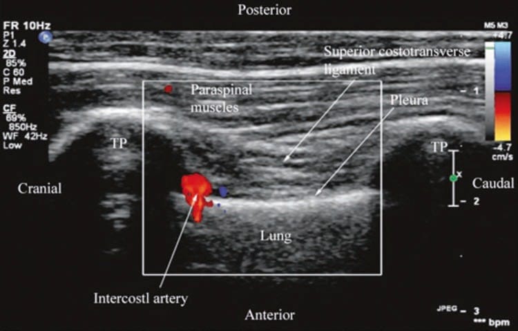
Fig. 13. Paramedian sagittal oblique sonogram of the thoracic paravertebral region showing the color Doppler signal from the intercostal artery in the paravertebral space. TP transverse process.
6. TECHNIQUES OF USG TPVB
Today there are no data or consensus on the best or safest approach for USG TPVB. Real-time USG TPVB can be performed using any one of the three different approaches described below.
Transverse Scan with Short Axis Needle Insertion (Technique 1)
In this technique, a transverse scan of the thoracic paravertebral region at the desired level is performed as described above, and the block needle is inserted in the short axis of the ultrasound beam (Fig. 14). During the scout scan, the depth to the transverse process and pleura is determined. The direction of needle insertion with this approach is similar to that when one performs a TPVB using surface anatomical landmarks. Since the needle is inserted in the short axis, it is visualized only as a bright spot, and the aim of this approach is to guide the needle to the TP. Once the TP is contacted, the needle is slightly withdrawn and readvanced by a predetermined distance of 1.5 cm so as to pass under the transverse process into the TPVS. After negative aspiration for blood or CSF, the calculated dose of local anesthetic is injected in aliquots. Following the injection it is common to see widening of the apex of the TPVS and anterior displacement of the pleura by the local anesthetic (Fig. 14). The local anesthetic may also spread to the posterior intercostal space laterally. Widening of the contiguous paravertebral spaces by the injected local anesthetic can also be visualized on a sagittal scan.
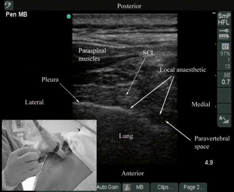
Fig. 14. Ultrasound-guided TPVB using a transverse scan in which the block needle is inserted in the short axis of the ultrasound plane (Technique 1). (Note the widening of the paravertebral space and anterior displacement of the pleura by the local anesthetic on the transverse sonogram. The local anesthetic is also seen to spread to the posterior intercostal space laterally. The picture in the inset shows how the transducer is oriented and the direction in which the needle is inserted. SCL superior costotransverse ligament).
Paramedian Sagittal Oblique Scan with In-Plane Needle Insertion (Technique 2)
In this approach, a paramedian sagittal oblique scan is performed as described above (Fig. 12), and the block needle is inserted in the plane of the ultrasound beam (Fig. 15). It is the author’s experience that, although the block needle is inserted in the plane of the ultrasound beam, it is often quite challenging to visualize the needle with this approach. This is in agreement with that reported by O’Riain et al. [29]. This may be because the block needle is often inserted at quite an acute angle and the ultrasound beam is also insonated with a slight oblique (outward) tilt for optimal visibility of the TPVS. Therefore, it is the author’s practice to advance the block needle under ultrasound guidance to contact the lower border of the TP, after which the needle is slightly withdrawn and readvanced so as to pass under the lower border of the TP. A test bolus of normal saline (2–3 ml) is then injected, and sonographic evidence (described above) is sought to ensure that the tip of the needle is in the TPVS. A calculated dose of local anesthetic is then injected in aliquots. Following the injection it is common to see anterior displacement of the pleura, widening of the paravertebral space, and an increased echogenicity of the pleura (Fig. 16) that are objective signs of a correct injection into the TPVS. The author has also observed, in real-time, the spread of the injected local anesthetic to the contiguous paravertebral spaces (Fig. 16) confirming previous reports that the contiguous TPVSs communicate with each other [3].
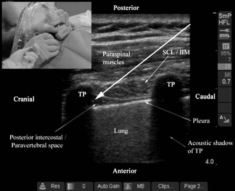
Fig. 15. Ultrasound-guided TPVB using a paramedian sagittal oblique scan (Technique 2). The long white arrow represents the direction in which the needle is inserted, and the picture in the inset shows how the block needle is inserted in the long axis of the ultrasound plane. Visualizing the block needle with this approach can be very challenging. TP transverse process, SCL superior costotransverse ligament, IIL internal intercostal membrane.
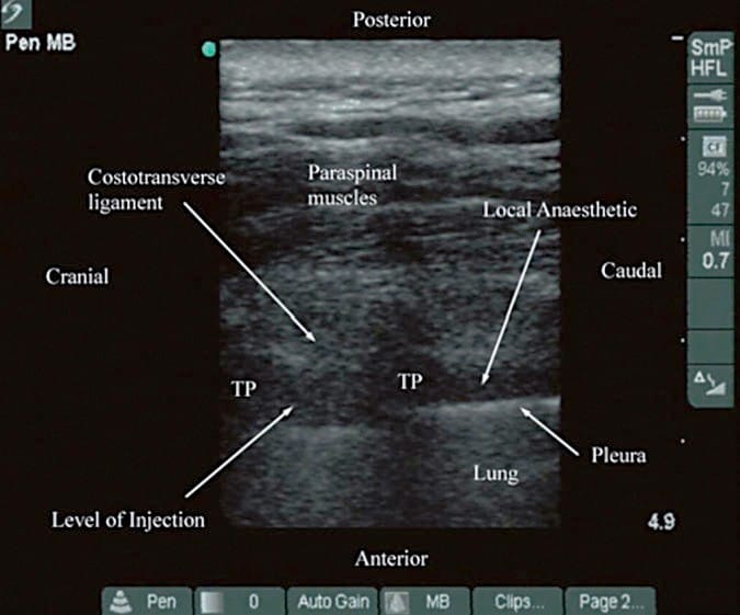
Fig. 16. Paramedian sagittal oblique sonogram of the TPVS after local anesthetic injection (Technique 2). (Note the widening of the paravertebral space and displacement of the pleura. The local anesthetic is also seen to have spread to the contiguous paravertebral space from the level of injection. TP transverse process).
Transverse Scan with In-Plane Needle Insertion or the Intercostal Approach to the TPVS (Technique 3)
In this approach, a transverse scan is performed as described above, and the block needle is inserted in the plane of the ultrasound beam from a lateral to medial direction (Fig. 17) until the tip of the block needle is seen to lie in the posterior intercostal space or the apex of the TPVS. A test bolus of normal saline (2–3 ml) is then injected, and sonographic evidence (described above) is sought to ensure that the tip of the needle is in the apical part of the TPVS. A calculated dose of local anesthetic is then slowly injected in aliquots. It is common to see widening of the paravertebral space and anterior displacement of the parietal pleura during the injection (Fig. 17). Compared with the other techniques described above, the block needle is best visualized with this approach since it is inserted in the plane of the ultrasound beam. However, since the needle is inserted from a lateral to medial direction, i.e., toward the intervertebral foramen, it may predispose to a higher incidence of epidural spread or inadvertent intrathecal injection [3]. Further research is required to confirm the safety and efficacy of this technique in clinical practice. Furthermore, since the block needle traverses the greatest amount of soft tissue, this approach also appears to cause the greatest amount of discomfort and pain to the patient during block placement and necessitates large doses of intravenous sedation and analgesia during multilevel paravertebral injections.
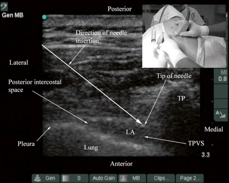
Fig. 17. Transverse sonogram of the TPVS after local anesthetic injection (Technique 3). (Note the widening of the paravertebral space, anterior displacement of the pleura, and spread of local anesthetic (LA) to the posterior intercostal space laterally. The long white arrow represents the direction in which the block needle is inserted. The picture in the inset shows how the block needle is inserted in the plane of the ultrasound beam from a lateral to medial direction. TP transverse process, TPVS thoracic paravertebral space).
7. CONCLUSION
Recent improvements in ultrasound technology and image processing capabilities of ultrasound machines have made it possible to image parts of the TPVS. Being able to delineate the relevant anatomy of the TPVS before and during a TPVB in real-time may offer several advantages. Ultrasound is non- invasive, safe, and simple to use, involves no radiation, and appears to be a promising alternative to traditional landmark-based techniques for TPVB. Using ultrasound one is able to preview the paravertebral anatomy prior to block placement and determine the depth to the transverse process and pleura. The latter defines the maximum safe depth for needle insertion and may help reduce the incidence of pleural puncture. Ultrasound guidance during TPVB also allows the block needle to be advanced accurately to the TPVS and visualize the distribution of the local anesthetic during the injection in real-time. This may translate into improved technical outcomes, higher success rates, and reduced needle-related complications. However, there is a need to establish an optimal axis for ultrasound imaging and needle insertion because visualization of the block needle during USG TPVB can be quite challenging. Ultrasound is also an excellent teaching tool for demonstrating the anatomy relevant for TPVB and has the potential to improve the learning curve of this technique. Currently, there are limited data on the use of ultrasound for TPVB, and further research is warranted to establish its role in clinical practice.
Acknowledgment: All figures in this article have been reproduced with permission from http://www.aic.cuhk.edu.hk/usgraweb.


PRACTICAL
Learn with Step-by-Step guide by the leading USPM experts

BE INSPIRED
Memorize ultrasound patterns with visual aids and create your own scripts with NOTES tool and never loose them.

UNDERSTAND
Every important aspect of ultrasound-guided pain interventions

READ OR LISTEN.
Learn according to your study style. Read or listen to the voiced-over material.